Download
1 / 26
270 likes | 393 Views
Ion Pickup Phenomenon upstream of Mars observed by ASPERA 3. M. Yamauchi. Scientific motivation. To understand ASPERA-3 data, it is extremely important to have the magnetic field ( B ) measurement.

E N D
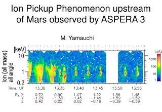
Ion Pickup Phenomenon upstream of Mars observed by ASPERA 3 M. Yamauchi
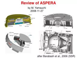
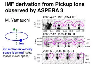
Scientific motivation To understand ASPERA-3 data, it is extremely important to have the magnetic field (B) measurement. However, Mars Express (MEX) does not have it (because of beaurocracy), and we could get it only for Venus Express. Therefore, Any method to estimate B is helpful. Use Mars Global Surveyor (MGS) data or Analyze gyromotion of ions observed by ASPERA/IMA because ion motion in velocity space is a ring! (spiral in real space)
Personal motivation Among many interesting phenomena seen in IMA data, the ring is one of the most "beautiful" looking in Quick Look. 2005-4-27 1331-1344 UT 2005-7-12 1133-1146 UT 2005-6-3 0602-0615 UT
In-coming directions of ions 0 3 6 9 12 15 6 5 Electric scan 4 IMA 3 Electric scan 2 1 14 0 3 6 9 12 15 0 15 Azimuth scan Elevation scan
Plot for single azimuth = 5~15 = 4 = 3 = 2 = 1 ring SW
H+ only (no He++) ! Ring H+ = 3 = 2 = 4 = 3 = 2 SW He++ SW H+
V0 = 0 , Viewing from +B Ions with V0=0 have initial perpendicular velocity to B = |VSW|cos() in SW rest frame, where sin() (= BX/B) is angle VSW & highest energy. The parallel velocity is constant in SW rest frame, and is zero in Martian frame
Selected ring data : ~ 1344~1347 UT *1) L = (0.05, -0.02, 1.00) in MSO *2) M = (0.94, -0.34, -0.06) in MSO *3) N = (0.34, 0.94, -0.003) in MSO
However, IMA orientation is not always ideal 2005-6-3 0545-0645 UT
In-coming directions of ions 0 3 6 9 12 15 6 5 Electric scan 4 IMA 3 Electric scan 2 1 14 0 3 6 9 12 15 0 15 Azimuth scan Elevation scan
Aligned in azimuthal direction Almost 1-D alignment Difficult to determine ring "plane"
From ring data at ~0623 UT (2005-6-3) VM (km/s) VL (km/s) VN (km/s)
V0 = 0 , Viewing from +B Ions with V0=0 have initial perpendicular velocity to B = |VSW|cos() in SW rest frame, where sin() (= BX/B) is angle VSW & highest energy. The parallel velocity is constant in SW rest frame, and is zero in Martian frame
Check item Alignment direction of the ring data by IMA ≈ Maximum variance direction (LX, LY, LZ) with LX << 1 For both V0 =0 & ≠0,B // (-1, 0, 0) xE // (0, LZ, -LY) IfL = evolution direction, sign(BZ) = - sign(LY) Tilt toward X (=) IfV0 = 0, two angles must be the same, i.e., * ' = angle between max energy (MAX) direction and solar wind direction , and ' = * Ratio k = VMAX/VSW= (MAX/SW)1/2 , and k = cos() Ifcos(') = k , most likely ' =
Selected ring data : ~ 0608 UT *1) L = (0.06, 0.99, 0.14) in MSO *2) M = (0.79, 0.04, -0.61) in MSO *3) N = (0.61, -0.15, 0.78) in MSO
Changing IMF is obtained ! 0608 UT, northward IMF, X tilt ~ +35°~40°, Y tilt ~ -10° 0613 UT, northward IMF, X tilt ~ +35°, Y tilt ~ -45° 0623 UT, northward IMF, X tilt ~ +20°, Y tilt ~ -30° 0633 UT, X tilt > +40°
Procedure (1) Manually select the ring distribution. (2) Apply the minimum variance method to determine L, M, and N. If the ring data is well arranged into a partial circle, ±N // B If not, (3) Examine |LX| < 0.3. If yes, L // -ESW. If not, remove the direction that corresponds to the lowest energy from the selected set of data and re-calculate a new L. (4) Manually obtain eMAX and '. (5) Check if MAX /4SW ≈cos2(') is satisfied. If yes, we have ≈ ', where BX/|B| = sin(). (6) If possible, identify the evolution direction and determine the sign of L and ESW. BT is parallel to VSWxESW.
summary Approximate IMF orientation can be derived from ring-like distributed protons as measured by the IMA Since the ring distribution represents a gyration trajectory (cycloid motion) of an ensemble of ions with nearly the same initial velocity (beam-like or zero velocity), the ring's plane must be perpendicular to the IMF. However, the actual derivation of the ring plane is very complicated due to the very limited viewing directions and angular resolution of the instrument.
IMF direction derived from cycloid-like ion distributions observed by Mars Express M. Yamauchi, Y. Futaana, R. Lundin, S. Barabash, M. Holmström (IRF-Kiruna, Sweden) A. Fedorov, J.-A. Sauvaud (CESR, Toulouse, France) R.A. Frahm, J.D. Winningham (SwRI, San Antonio, USA) E. Dubinin (MPS, Katlenburg-Lindau, Germany), Kallio (FMI, Helsinki, Finland) and ASPERA-3 team
summary MEX/IMA often observed cycloid distributions (two-dimensional partial ring distributions in velocity phase space) of protons upstream of the Martian bow shock. Since ions are expected to gyrate around the IMF in velocity phase space when the IMF is relatively uniform on a scale larger than the gyroradius, it is in principle possible to derive the IMF orientation from the observed cycloid distributions. We show this method which has three steps: (1) Manually choose the ring data (it is one of the minor populations and is difficult to select automatically). (2) Apply the minimum variance method to the selected ring data to determine the ring plane. (3) After the quality check, use either: (a) the minimum variance directionN as the IMF orientation or (b) maximum variance direction L as the interplanetary electric field orientation. In the latter case, the tilt angle of IMF toward the X direction from the Y-Z plane is obtained from two methods when the selected ring distribution is newly ionized hydrogen atoms: (i) angle between the velocity of the ring's maximum energy portion and the solar wind vector, and (ii) energy ratio between the solar wind and the maximum energy of the ring.