Download
1 / 18
180 likes | 332 Views
IMF direction derived from cycloid-like ion distributions observed by Mars Express. M. Yamauchi, Y. Futaana , R. Lundin, S. Barabash, M. Holmström (IRF-Kiruna, Sweden) A. Fedorov, J.-A. Sauvaud (CESR, Toulouse, France) R.A. Frahm, J.D. Winningham (SwRI, San Antonio, USA)

E N D
IMF direction derived from cycloid-like ion distributions observed by Mars Express M. Yamauchi, Y. Futaana, R. Lundin, S. Barabash, M. Holmström (IRF-Kiruna, Sweden) A. Fedorov, J.-A. Sauvaud (CESR, Toulouse, France) R.A. Frahm, J.D. Winningham (SwRI, San Antonio, USA) E. Dubinin (MPS, Katlenburg-Lindau, Germany), E. Kallio (FMI, Helsinki, Finland) and ASPERA-3 team
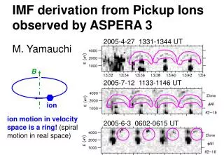
Actually, the ring distribution is the "clearest signature" among many interesting phenomena seen in IMA Quick Look (mass and azimuth are integrated) Motivation To understand Mars Express (MEX) hot plasma and energetic neutral atom (ASPERA-3) data, it is important to have the magnetic field (B) measurement. However, MEX does not measure B (because of bureaucracy), and B is measured only on Venus Express. Therefore, any method to estimate B on MEX is helpful. Using Mars Global Surveyor (MGS) data is one method, but we here take another approach : 2005-4-27 1331-1344 UT 2005-7-12 1133-1146 UT Analyze gyromotion of ions observed by ASPERA-3 ion mass analyser (IMA) becauseion motion in velocity space is a ring! (spiral motion in real space) B 2005-6-3 0602-0615 UT ion
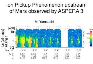
2005-4-27 (easy case) single azimuth plots average BS average IMB = 5~15 = 4 = 3 = 2 = 1 Mars ring MEX orbit (light blue) during 1329-1357 UT in the cylindrical MSO coordinates. R2 = Y2+Z2. Mars SW IMA energy-time spectrograms for proton cannel at 0.7-7 keV during 1334:00-1343:40 UT on 27 April 2005. Five different azimuthal sectors (φ) are presented except sector 0. The nearly 3-min cycle seen in the IMA data is due to the electric scan of the entrance direction from nearly -45° (elevation=0) to nearly +45° (elevation=15). The counts that are seen above the solar wind in the proton channel are due to contamination from alpha particles.
Viewing from +B Ion motion with V0=0 VZ V*Z 3-D view B VY V*Y V*X velocity space trajectory VX V (SW frame) = V* (Martian frame) + VSW Ions with V0=0 in Martian frame have an initial velocity -VSW in SW rest frame where E (electric field) =0. Ions in SW rest frame make simple spiral trajectory (simple gyration + constant parallel velocity), i.e, a simple ring in velocity space as indicated by blue dashed lines. Ring = within a plane the minimum variance direction (N) is parallel to B! Initial velocity to B is V0cos Viewing from +E
Velocity (in km/s) scatter plots of the H+ data (mass range 0.5-1.1: slightly contaminated by SW He++) during 1334-1357 UT, 27 April 2005, in (a) MSO coordinates, and maximum(L)-medium(M)-minimum(L) variance coordinates determined from (b) manually selected ring data, and (c) automatically filtered data during 1337-1357 UT. Azimuth=0 data are not shown (total 450 points). The circles and triangles denote the points belonging to the ring distribution by a manual inspection, with circles corresponding to 7-40 counts, filled triangles corresponding to more than 40 counts, and empty triangles corresponding to 4-6 counts. Non-ring data are shown using plus marks (blue: count is 7-40, light blue: count more than 40). Coordinates given (b) arranges the ring data fitting to a circle best passing through the origin.
However, IMA orientation is not always ideal IMA all-mass & all-azimuth data on 2005-6-3 , 0545-0645 UT Aligned in the azimuthal direction (points 2, 3, 4, 5 in the ion-motion illustration) Linear alignment (small data range in M direction) Minimum variance method gives clear L direction (// ±E), but not M & N directions. We may not use ±N as estimate of B direction, but (1) E x VSW gives BY/BZ orientation ! (2) BX/B (or ) can be obtained intuitively =5~14=15 =1 =2 =3 =4 IMA light ion (H+ and He++) data (3~8 keV) for each azimuth at ~0608 UT & ~0623 UT
cf. beam-origin (V0 ≠ 0) ring distribution case Alignment direction of the ring data by IMA ≈ Maximum variance direction (LX, LY, LZ) where LX << 1 BT=(0, BY, BZ) // VSWxE // (0, LZ, -LY) Sign of B IfL = evolution direction, sign(BZ) = - sign(LY) Tilt toward X (=) * ' = angle between max energy (MAX) direction and solar wind direction * Ratio k = VMAX/VSW= (MAX/SW)1/2 IfV0 = 0, two angles must be the same, i.e., ' = , and k = cos() Ifcos(') = k , most likely = ' MAX
Procedure & result Using (1)~(2) Constant IMF for 2005-4-27 event 1336-1357 UT, dawn-dusk oriented IMF, with X tilt ~ 20° (1) Manually select the ring distribution. (2) Apply the minimum variance method to determine L, M, and N. Ifthe ring data is well arranged into a partial circle, ±N // B If not, (3) Examine |LX| < 0.3. If yes,L // -ESW. If not, remove the direction that corresponds to the lowest energy from the selected set of data and re-calculate a new L. (4) Manually obtain MAX and '. (5) Check if MAX /4SW ≈cos2(') is satisfied. If yes, we have ≈ ', where BX/|B| = sin(). (6)If possible, identify the evolution direction and determine the sign of L andESW. BT is parallel to VSWxESW. Using (3)~(6) Changing IMF for 2005-6-3 event 0608 UT, northward IMF, X tilt ~ +35°~40°, Y tilt ~ -10° 0613 UT, northward IMF, X tilt ~ +35°, Y tilt ~ -45° 0623 UT, northward IMF, X tilt ~ +20°, Y tilt ~ -30° 0633 UT, X tilt > +40°
In-coming directions of ions 0 3 6 9 12 15 6 5 Electric scan 4 IMA 3 Electric scan 2 1 14 0 3 6 9 12 15 0 15 Azimuth scan Elevation scan
summary MEX/IMA often observed partial ring distributions of protons in velocity space upstream of the Martian bow shock. Since ions are expected to gyrate around the IMF in velocity phase space, an ensemble of ions with nearly the same initial velocity (beam-like or zero velocity) forms such ring distribution when the IMF is relatively constant over a gyroperiod. Inversely, approximate IMF orientation can be derived from the observed ring distribution because the ring's plane must be perpendicular to the IMF. However, the actual derivation of the ring plane is very complicated because (a) the ring distribution is just one of minor component that IMA detects, and (b) IMA's viewing directions and angular resolution are very limited. Therefore, we developed method to obtain the IMF orientation from actual IMA data (see "procedure" above). There are three important steps: (1) Manually choose the ring data with the same V0: (automatic selection does not work). (2) Obtain maximum (L) and minimum (N) direction from the selected ring data. (3) After the quality check, use either N or L (see procedure). We applied actual IMA data. Two examples (2005-4-27 and 2005-6-3) are shown. It is possible to obtain the IMF orientation about 75% of BS traverals when IMA is in the best operation mode (highest post-acceleration to detect proton).
2005-4-27, 1344-1347 UT Selected ring data *1) L = (0.05, -0.02, 1.00) in MSO *2) M = (0.94, -0.34, -0.06) in MSO *3) N = (0.34, 0.94, -0.003) in MSO 2005-6-3, ~0608 UT *1) L = (0.06, 0.99, 0.14) in MSO *2) M = (0.79, 0.04, -0.61) in MSO *3) N = (0.61, -0.15, 0.78) in MSO
H+ only (no He++) ! Ring H+ = 3 = 2 = 4 = 3 = 2 SW He++ SW H+
From ring data at ~0623 UT (2005-6-3) VM (km/s) VL (km/s) VN (km/s)
2005-4-27 (easy case) ring SW
However, IMA orientation is not always ideal 2005-6-3 0545-0645 UT