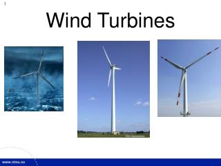
Designing Control Systems for Wind Turbines
580 likes | 1.23k Views
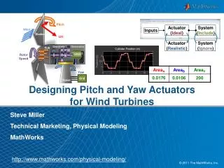
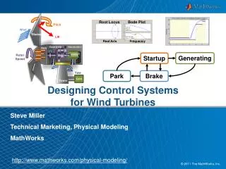
Root Locus. Bode Plot. Real Axis. Frequency. Designing Control Systems for Wind Turbines. Pitch. Wind. Blades. Lift. Generating. Startup. Geartrain. Generator. Hub. Park. Brake. Rotor Speed. Steve Miller Technical Marketing, Physical Modeling MathWorks. Yaw. Tower. Grid.

Designing Control Systems for Wind Turbines
E N D
Presentation Transcript
Root Locus Bode Plot Real Axis Frequency DesigningControl Systemsfor Wind Turbines Pitch Wind Blades Lift Generating Startup Geartrain Generator Hub Park Brake RotorSpeed Steve Miller Technical Marketing, Physical Modeling MathWorks Yaw Tower Grid http://www.mathworks.com/physical-modeling/
+ - Root Locus Bode Plot Real Axis Frequency Key Points • The time to develop a controlsystem can be shortened byusing control design tools • Optimizingsystemswithrespectto design requirementsleadsto optimal design choices • Finding errors in supervisorycontrollers requires a modelthat can be easily built, understood, and tested Ax + Bu Control
Agenda • Wind turbine control system overview • Compensator design for pitch control system • Using linear control theory • Applying optimization algorithms to nonlinear model • Supervisory control using state machines
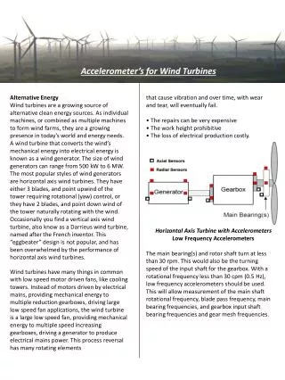
Wind Turbine Control Systems • Blade pitchcontrolsystem • Adjustpitch angle toregulaterotationalspeed • Supervisorycontrolsystem • Analyzeoperatingconditionstodeterminestateofturbinetoenable/disableoperation Pitch Wind Lift, Drag Blades Nacelle Generator Geartrain Hub RotorSpeed GeneratorSpeed Yaw Grid Tower
Controlling Rotor SpeedUsing the Pitch Angle Model: + - Pitch Lift RotorSpeed Problem:Control the pitch angle so that the generator shaftspins at nominal speed Solution: Use Simulink to determine the pitch angle by controlling the angle of attack DesiredRotor Speed Pitch AngleCommand Desired AngleofAttack Control InflowAngle ActualRotor Speed
Overview of Pitch System Event Based Control System changes mode based on events Pitch AngleCommand DetermineState Control Actuator Measured Pitch Angle Compensator Design Actuation is based on deviation from a commanded value (PID, etc.)
Agenda • Wind turbine control system overview • Compensator design for pitch control system • Using linear control theory • Applying optimization algorithms to nonlinear model • Supervisory control using state machines
+ + - - Ax + Bu Root Locus Bode Plot Real Axis Frequency Possibilities for Compensator Design • Linear ControlTheory • Linearize system using Simulink Control Design • Perform linear control design with Control System Toolbox • Retest controller in nonlinear system • Specify System Response • Specify response characteristics • Automatic tuning using Simulink Design Optimization Control Control
Pitch Angle Command Force Error + - Ax + Bu Root Locus Bode Plot Real Axis Frequency Control Design on Linearized Plants Model: Control Problem:Design and test a controller for a nonlinear system using linear methods tomeetsystemspecifications Solution:Use Simulink Control Design and Control System Toolbox to design, tune, and test the controller
+ - Ax + Bu = 0 Root Locus Bode Plot Real Axis Frequency Control Design on Linearized Plants • Steps to Design Controller 1. Identify control loops of interest 2. Identify operating point 3. Linearize model about this point 4. Perform control design 5. Test controller in nonlinear system Actuator Force Pitch Angle Command Control
Control Design on Linearized Plants • Advantages of Simulink Control Design and Control System Toolbox • Enable easy application of linear control theory • Operating points from specification or simulation • Graphical design with interactive plots • Rapid evaluation of designs with interactive analysis plots • Automatic tuning of parameters through various methods (PID, IMC, LQG) saves time • Optimize performance based on time, frequency, or root locus constraints
Agenda • Wind turbine control system overview • Compensator design for pitch control system • Using linear control theory • Applying optimization algorithms to nonlinear model • Supervisory control using state machines
+ - Compensator Design on Nonlinear Plants Model: (Kps+Ki) s Problem:Design and tune the controller in this system to meet system requirements Solution:Use Simulink Design Optimization to design, tune, and test the controller (Kps+Ki) s
Compensator Design on Nonlinear Plants • Steps to Optimize Response 1. Identify parameters to be tuned and their ranges 2. Specify desired response 3. Perform response optimization (Kps+Ki) s
Compensator Design on Nonlinear Plants • Advantages of Simulink Design Optimization • Graphical interface makes it easy to map specification to tests. • Automatic tuning of parameters saves time. • Simulating plant and controller in one tool allows engineers to understand and optimize performance of the entire system.
Agenda • Wind turbine control system overview • Compensator design for pitch control system • Using linear control theory • Applying optimization algorithms to nonlinear model • Supervisory control using state machines
Model the SupervisoryControl of the Wind Turbine Model: Startup Generating turbine > min speed wind > cut in speed && wind < cut out speed park brake = 0pitchbrake = 0 generator = 0 park brake = 0pitchbrake = 0 generator = 1 wind spd < min spd|| wind spd > maxspd|| turbinespd < min spd || turbinespd > maxspd Turbine spd< park spd Park Brake park brake = 1pitchbrake = 0 generator = 0 park brake = 0pitchbrake = 1 generator = 0 Problem:Create a supervisory controller that sets the state of the brake, generator, and pitch angle based on turbine conditions Solution: Use Stateflow to model the event-based controller
+ - Root Locus Bode Plot Real Axis Frequency Key Points • The time to develop a controlsystem can be shortened byusing control design tools • Optimizingsystemswithrespectto design requirementsleadsto optimal design choices • Finding errors in supervisorycontrollers requires a modelthat can be easily built, understood, and tested Ax + Bu Control