Download
1 / 44
440 likes | 614 Views
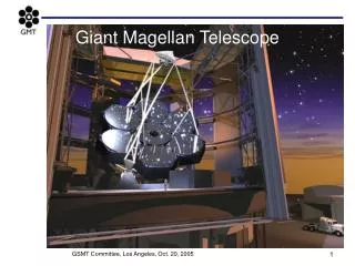
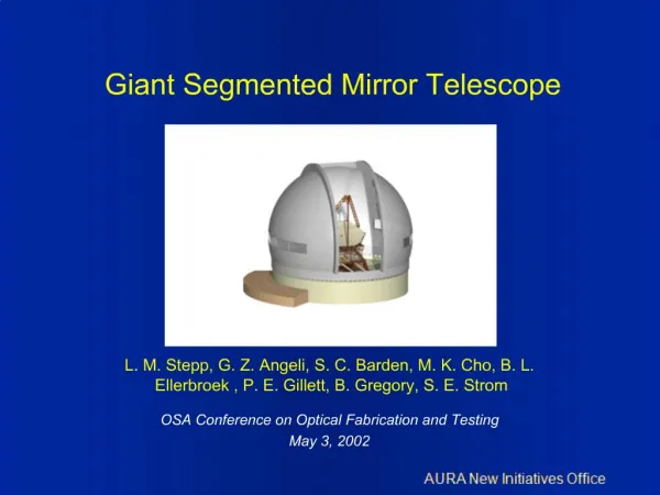
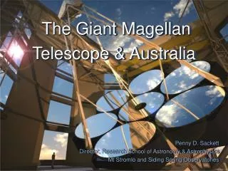
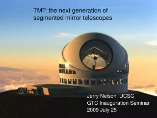
The Giant Segmented Mirror Telescope. The USA Decadal Review. In May 2000, the US astronomy decadal review committee recommended, as its highest priority ground-based initiative, the construction of a 30-meter Giant Segmented Mirror Telescope (GSMT)

E N D
The USA Decadal Review • In May 2000, the US astronomy decadal review committee recommended, as its highest priority ground-based initiative, the construction of a 30-meter Giant Segmented Mirror Telescope (GSMT) • In response, AURA formed a New Initiatives Office (NIO) to support scientific and technical studies leading to the creation of a GSMT • NIO is a joint venture of the National Optical Astronomy Observatory (NOAO) and the Gemini Observatory • Goal is to ensure broad astronomy community access to a 30m telescope contemporary with NGST.
N IO Organization NIO Management Board William Smith -- President of AURA Jeremy Mould -- Director of NOAO Matt Mountain -- Director of Gemini Observatory Project Scientist Steve Strom Program Manager Larry Stepp System Scientist Brooke Gregory Admin. Assistant Jennifer Purcell Opto-Mechanical Myung Cho Controls George Angeli Adaptive Optics Ellerbroek - Gemini Instruments Barden - NOAO Mechanical Designer Rick Robles Structures Paul Gillett Optics Hansen - Gemini Sites Walker - NOAO
AURA New Initiatives OfficeApproach to GSMT Design Three Parallel efforts: • Understand the scientific context for GSMT in NGST / ALMA era • Develop the key science requirements • Address challenges common to all ELTs • Site testing and selection • Cost-effective segment fabrication • Characterization of wind loading • Hierarchical control systems • Adaptive optics • Cost control techniques • Develop a Point Design • Based on initial science goals & instrument concepts
Site Testing and Selection • Survey of candidate sites by remote sensing (satellite data) • Regions of interest: • Mauna Kea • Western United States and Mexico • Chile • Parameters determined: • Cloud cover • Precipitable water vapor • Collaborators: • Cornell • ESO • University of Tokyo • CELT • UNAM & INAOE (Mexico)
Site Testing and Selection • Construction of turbulence profilometer (MASS – Multi-Aperture Scintillation Sensor) • Uses scintillation measurements of a single star to measure: • Isoplanatic angle, characteristic strengths and altitudes of the few dominant turbulence layers • Integral seeing producing by the whole atmosphere
Site Testing and Selection • Atmospheric turbulence modeling and measuring • Direct measurements of seeing and wind speed • Computational fluid dynamics • Collaborators • CELT • UNAM (Mexico) • Cornell Digital elevation model of Chajnantor region
Site Testing and Selection • Sodium layer measurements at Cerro Tololo • Collaborating on Gemini study to answer questions about variation of sodium layer height, thickness and column density with: • Latitude • Season • Time of night 300mw laser launched from laser room on Cerro Tololo
Characterization of Wind LoadingTest at Gemini South • Opportunity arose during integration of Gemini South to do a full-scale wind test in realistic conditions • Gemini enclosure has large vent gates – permits testing a range of enclosure conditions • Gemini dummy mirror has equivalent properties as the real primary mirror, but can be instrumented • Gemini M1 is above the EL axis - open to the wind flow (similar to concepts for future larger telescopes)
Sensor locations 3-axis anemometers Pressure sensors, 32 places
Ultrasonic anemometer Ultrasonic anemometer Pressure sensors Sensor Locations
Simultaneous Animations(c00030oo) Wind Pressure (N/m2) Mirror Deformation (microns) Wind Speed at 5 Locations (m/sec)
Controls Approach: Hierarchical Subsystems ~100 ~50 ~20 ~10 2 LGS MCAO spatial & temporal avg Zernike modes AO (M2) spatial & temporal avg aO (M1) spatial avg temporal avg spatial avg Secondary rigid body spatial & temporal avg Main Axes 0.001 0.01 0.1 1 10 100 Bandwidth [Hz]
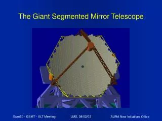
Point DesignKey Features • Fast aspheric primary • Stigmatic image after two reflections • Radio telescope-type design • Structural advantages • Accommodates large instruments • Adaptive secondary • Wind-buffeting compensation • Atmospheric correction in IR, with low emissivity • First stage in higher-order adaptive systems • Prime focus instrument • Convenient plate scale for seeing-limited observations • Enables wide-field science
Optical Design Optical design: Classical Cassegrain M1 diameter: 30 meters M1 focal ratio: f/1 M2 diameter: 2 meters M2 focal ratio: f/18.75
Radio Telescope Structural Design • Lightweight steel truss structure • Fast primary focal ratio • Small secondary mirror • M2 supported on tripod structure • Elevation axis behind M1 • Span between elevation bearings is less than M1 diameter • Allows direct load path
Initial Point Design Structure Concept developed by Joe Antebi of Simpson Gumpertz & Heger • Based on radio telescope • Space frame truss • Single counterweight • Cross bracing of M2 support
Initial Point Design Structure Plan View of StructurePattern of segments Gemini
Initial Structural Analysis Horizon Pointing - Mode 1 = 2.16 Hz
A Few Parameters from the Structural Analysis • Total weight of elevation structure – 700 tonnes • Total moving weight – 1400 tonnes • Gravity deflections ~ 5-25 mm • Primarily rigid-body tilt of elevation structure • Lowest resonant frequencies ~ 2 Hz Large size and low resonant frequency make wind buffeting a key issue.
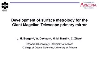
Primary Mirror Segments • Segment dimensions • 1.15-m across flats -- 1.33-m corner to corner • 50 mm thickness • Number of segments: 618 • Maximum departure from sphere 110 microns • Comparable to Keck • Axial support is 18-point whiffletree • FEA Gravity deflection 15 nm RMS
Stray Light BafflesIf Needed Primary baffle: 14 m long Secondary baffle: 3 m diamater Fully baffled field of view: 5 arc min
Controllable Elements Active Systems: • M2 rigid body motion • ~ 5-10 Hz • Five axes • M1 segment rigid body position • ~ 1 Hz • Piston, tip & tilt • M1 segment figure control • Based on look-up table ~ 0.1 Hz • Astigmatism, focus, trefoil, coma • Active structural elements • Active alignment • Active damping
Controllable Elements Adaptive Systems: • Adaptive mirror in prime focus corrector • Adaptive secondary mirror • ~ 20-50 Hz • ~ 2400 actuators • Multi-conjugate wide-field AO • ~ 3 DMs; ~ 8500 actuators • Laser Guide Stars • High-order narrow-field conventional AO • ~ 10,000 – 50,000 actuators
Active and Adaptive Optics will be integrated into Telescope and Instrument concepts from the start.
Instruments • NIO currently developing design concepts for 5 instruments: • Multi-Object, Multi-Fiber, Optical Spectrograph – MOMFOS • Near IR Deployable Integral Field Spectrograph – NIRDIF • MCAO-fed near-IR imager • Mid-IR, High Dispersion, AO Spectrograph – MIHDAS • Diffraction-Limited Near IR Coronagraph
Multi-Object Multi-Fiber Optical Spectrograph(MOMFOS) Located at prime focus
Multi-Object Multi-Fiber Optical Spectrograph(MOMFOS) Located at prime focus
Diffraction-limited Coronagraph Located at co-moving Cassegrain focus
Mayall, Gemini and GSMT Enclosuresat same scale Mayall GSMT Gemini
Plans for the Next 10 Months • Complete “GSMT Book” in electronic form – will be available next month at: www.aura-nio.noao.edu • Involve community in understanding GSMT scientific context • Continue work on point design • Develop integrated modeling of telescope response to disturbances (mainly wind) • Continue site testing efforts • Develop cost estimates & cost-reduction strategies
Plans for the Next 10 Months • Develop collaborations to work on: • Site testing • Segment fabrication methods • Characterization of wind loading • Adaptive optics • Development of cost estimates and estimating methods • Build partnership to proceed with GSMT design