Download
1 / 13
150 likes | 307 Views
Pointing Control for a giant segmented mirror telescope. Patrick Wallace Rutherford Appleton Laboratory United Kingdom. Presentation Outline. Platforms Software GSMT Challenges. TCS Platforms.

E N D
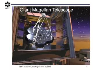
Pointing Controlfor a giant segmented mirror telescope Patrick Wallace Rutherford Appleton Laboratory United Kingdom
Presentation Outline • Platforms • Software • GSMT Challenges
TCS Platforms • Use mass-market hardware and software: PC, running Linux/RTL or even Windows. C++, Java, CORBA. Avoid expensive RTOS, minority-interest middleware and specialized hardware. • Work mostly on the “Unix side”: use strict real-time only when necessary; use computers as intelligent managers, not as mere “programmable hardware”.
TCS Design Philosophy • The science requirements, plus observing scenarios, merely sample the required functionality. • The TCS must deliver those functions as points in a “functionality envelope”. • The different modes of operation come from parametric control of a single, integrated, system. • As far as possible, all the code runs all the time.
Specifying the Pointing • Not simply where the optical axis is aimed. • The user tells the TCS three things: • where in the sky to look • where in the focal plane the image is to fall • which way up the image is to be • The TCS predicts the mount and rotator angle demands that will realize the specified image.
The Pointing Flow • Starts with target position. • Astronomical transformations lead to “observed” [Az,El]. • Allowing for non-perpendicularities, flexures and other pointing effects produces the required mount angles.
Pointing “Filters” • Science pointing current pointing: • imposes offsetting speed limit • Current pointing mount pointing: • apportions motion between mount and M2 • Guider pointing model: • offloads M2 bias • All filters have adjustable time constants etc. to achieve a variety of effects.
TCS/Mount Interface • TCS sends timestamped mount coordinates over a LAN at (say) 20 Hz, defining locus. • Mount gets its position/velocity/acceleration demands by interpolation, using the last two or three TCS demands. • Same “locus” strategy for rotator, guide probes, even M2 in principle.
mount coordinates “Virtual Telescope” target direction pointing origin celestial transformation pointing model position angle
Guiding • Each guider is a separate “virtual telescope”. • Given the guide star [,], the current mount demands define the [x,y] we want the guide star image to occupy. • Differential refraction and atmospheric dispersion are taken care of automatically. • The guider system is more important than the mount in pinning down the WCS.
World Coordinates • Predicting [x,y][,] is the objective. • Using the current pointing state, the TCS generates the transformation describing the focal plane in [x,y][,] terms. • Packaged support for transformation to instrument coordinates and for writing FITS headers is also required.
GSMT Challenges • In terms of pointing, not much is new in fact. • Pointing integrity must extend into AO, including adaptive M2. • Probably not possible to locate the rotator axis; the guider probes will define the WCS, so calibration methods need attention. And/or peripheral CCDs? • Encoders not enough. Need accelerometers and structural sensors. • 10 mas PSF means variable refraction across the pupil and atmospheric dispersion need attention.
The “Servo Engineer” Problem • How do you keep your servo engineer(s) between the design phase and telescope commissioning? • Alternatively, how can the knowledge be mothballed during the construction phase?