Download
1 / 24
260 likes | 442 Views
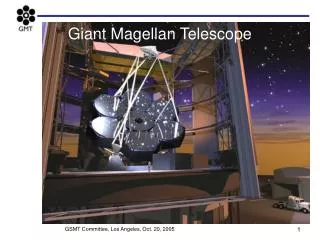
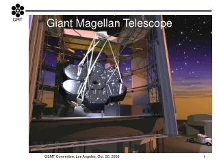
Development of surface metrology for the Giant Magellan Telescope primary mirror. J. H. Burge a,b , W. Davison a , H. M. Martin a , C. Zhao b a Steward Observatory, University of Arizona b College of Optical Sciences, University of Arizona. GMT primary mirror segments.

E N D
Development of surface metrology for the Giant Magellan Telescope primary mirror J. H. Burgea,b, W. Davisona, H. M. Martina, C. Zhaob aSteward Observatory, University of Arizona bCollege of Optical Sciences, University of Arizona
GMT primary mirror segments • 25 meter telescope, requires 7 mirror segments • Each mirror segment is 8.4 meters in diameter • The off axis segments have 14.5 mm aspheric departure
Principal measurement using interferometer and reflective null corrector with CGH Interferometer at M1 center of curvature
Test tower at Steward Observatory Mirror Lab New tower Original tower New tower 28 meters tall, 80 tons of steel floated on 400 ton concrete pad accommodates other UA projects (LBT, LSST) lowest resonance of 4.8 Hz with 9 ton 3.75-m fold sphere + cell
New test tower at Mirror Lab Test optics for GMT segment Test of 3.75 m fold sphere 28 m vibration-isolated tower was installed 2006-07. Supports all GMT tests, plus LSST, future 6.5 m and 8.4 m mirrors. GMT off-axis segment
Measurement of center segment The center segment can be measured by tilting the fold sphere to point straight down, then a small computer generated hologram will compensate the residual errors. Cone defined by light from outer edge of mirror 50 mm CGHcompensates only 20µm aspheric departure Cone defined by light from edge of central hole Vibration insensitive interferometer
Optics of Sam Insert a CGH to test Sam Point source microscope aligned to M2 ~1.5 m Interferometer forGMT measurements CGH M2
M2 is aligned to CGH Point Source Microscope M2 CoC reference ball M2 CoC reference ball To M2 Computergenerated hologram CGH and M2 CoC reference ball are aligned using CMM to 10 µm M2 aligned to CoC reference ball using PSM
Use of a Point Source Microscope to align M2 • Use cradle to locate ball at location where M2 center of curvature should be(cradle geometry defined by CMM) • PSM is adjusted to the ball • The ball is then removed. The PSM is looking at mirror directly. • Adjust the mirror until reflection from it is focused on the same spot as the ball on the camera
Interferometer alignment to CGH • Use return into interferometer from reference patterns on CGH for • tilt (using fold flat) • shifting interferometer for focus
CGH test of Sam • CGH inserted into light coming from Sam • Reflection back through system is used to verify wavefront • CGH mounted on invar plate with other references for M1 alignment
Alignment of M1, GMT • M1 is aligned to Sam with ~100 µm tolerances • Reference hologram is aligned to Sam. Then it is used to represent Sam. • A laser tracker measures the 3-space position of the reference hologram and M1. • M1 is aligned to the reference hologram according to the measurements. • The laser tracker also provides the reference for the GMT location in the test
References co-aligned with CGH CGH, coaligned with: Corner cube tracker reference Flat mirror, angular reference for tracker
Alignment error budget Effect on primary mirror segment in telescope
3.75 m fold sphere • Figure of fold sphere will be measured in situ and subtracted. • Accuracy of correction depends on slope errors, and magnitude of small-scale structure that cannot be subtracted. • Finished fold sphere meets requirements: • < 2 nm/cm rms slope error • small-scale errors < 15% of GMT segment specification • Overall accuracy < 20 nm rms over clear aperture. Cast in the Mirror Lab spinning oven Polished at the Mirror Lab Coated at Kitt Peak
Support of fold sphere 3750 mm mm 455 mm mm Hangs from “Active” support, allowing quasi-static force adjustment based on in situ measurement
Scanning pentaprism test Pentaprism rail lies in plane perpendicular to parent axis. Hub rotates rail to scan different diameters. Scanning pentaprism test as implemented for GMT off-axis segments. Pentaprism rail is suspended from tower. Scanning pentaprism measures slope errors by producing collimated beams parallel to parent axis. Displacement of focused spot is measured with camera in focal plane.
interferometric test pentaprism measurement Pentaprism test of 1.7 m off-axis NST mirror • 1/5 scale GMT pentaprism test • This was done in late 2007 before the mirror was finished. • The pentaprism test only samples lowest order aberrations • The PP results agree with results from interferometry Poster paper by P.Su et al nm surface
Laser Tracker Plus laser tracker & distance-measuring interferometers (DMI) sphere-mounted retro-reflector for laser tracker laser tracker DMI laser and remote receivers PSD 10% BS DMIs Retroreflector for interferometer and position sensing detector (PSD) assemblies in 4 places at edge of mirror DMI retroreflector Poster paper by T. Zobrist et al
Laser Tracker Plus measurement of3.75 m fold sphere M1 • R = 25.5 m, tracker distance = 22 m • 93 sample points, measured 4 DMIs with each sample • Subtracted best-fit sphere (R = 25.497 m) before DMI correction: 1.4 μm rms after DMI correction: 0.75 μm rms
Shear test Each segment has axisymmetry about parent axis Rotate segment about this axis under the optical test and separate effects that move with the mirror from those that remain with the test.
Summary • We are building the hardware to measure the GMT segments. • We expect to meet a tight error budget • Low order modes controlled by active optics, using < 5% Force • Uncorrectable features fit well within the allotted GMT PM structure function • We take this problem seriously and have implemented a comprehensive set of crosschecks • Scanning pentaprism system • Laser tracker Plus • Shear test We have invested in metrology for making the first of the segments. Others will be made at low risk, low cost.