MEMS DEVICE WAFER LEVEL PACKAGING TECHNICAL PRESENTATION
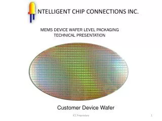
MEMS DEVICE WAFER LEVEL PACKAGING TECHNICAL PRESENTATION. Customer Device Wafer. TECHNICAL PROPOSAL FOR ULTRASOUND MEMS DEVICE WLP. Process Modification Required as follows:. Reduction of Bond pads to half of existing bond pads size.

MEMS DEVICE WAFER LEVEL PACKAGING TECHNICAL PRESENTATION
E N D
Presentation Transcript
MEMS DEVICE WAFER LEVEL PACKAGING TECHNICAL PRESENTATION Customer Device Wafer ICC Proprietary
TECHNICAL PROPOSAL FOR ULTRASOUND MEMS DEVICE WLP Process Modification Required as follows: • Reduction of Bond pads to half of existing bond pads size. • - Since bond pad size has been reduced, the distance between 2 chip isolation lines will • be more now and additional scribing / dicing area can be provided for our SWP Process Flow Changes: New smaller Bond PadsPassivation Bond Pad Opening Testing Ship Wafers to ICC ICC Proprietary
TECHNICAL PROPOSAL FOR MEMS DEVICE WLP Chip 1 Chip1 ICC Proprietary
TECHNICAL PROPOSAL FOR MEMS DEVICE WLP Chip 1 Chip 1 ICC Proprietary
Schematic plan showing a possible EXISTING chip configuration Active Area Chip 1 Bond Pads Scribe / Dicing Area Chip 2 Isolation line Chip 3 Bond pad size = 100 micron Sq. Chip 4 ICC Proprietary
Proposed NEW chip configuration Active Area Chip 2a New Bond Pads Scribe / Dicing Area Chip 2a Chip 2a Bond pad size = half original pad ICC Proprietary
Proposed NEW chip configuration Chip 2a Bond pad size = 50 micron Sq. With 20 micron Sq Opening at center. ICC Proprietary
Proposed NEW chip configuration Chip 2a Chip 2a Via fabrication At the scribe zone Via Size 20um Sq. X 50 um ICC Proprietary
Proposed NEW chip configuration Chip 2a Via passivation PECVD process Chip 2a ICC Proprietary
Proposed NEW chip configuration Chip 2a Chip 2a Interconnection At the scribe zone ICC Proprietary
Proposed NEW chip configuration Chip 2a Chip 2a Top Passivation layer ICC Proprietary
Proposed NEW chip configuration Chip 2a Chip 2a Glass wafer Bonding ICC Proprietary
Proposed NEW chip configuration Backside of the Wafer after Back grinding and polishing ICC Proprietary
Proposed NEW chip configuration 1stPassivation on backside ICC Proprietary
Proposed NEW chip configuration Back side pad opening ICC Proprietary
Proposed NEW chip configuration Routing to new Bump pads ICC Proprietary
Proposed NEW chip configuration 2ndPassivation Film on bump pads ICC Proprietary
Proposed NEW chip configuration UBM pads ICC Proprietary
Proposed NEW chip configuration Solder Bumping ICC Proprietary
ICC Proprietary Proposed NEW chip configuration Dicing Process ICC Proprietary