Ground Control
Ground Control. Jordan Hodge Jordan Lyford Wilson Schreiber. Contents. Background Problem Statement Solution SoftWare/Electrical Mechanical Azimuth Elevation Concepts Static and Dynamics of System System Diagram Timeline Responsibilities Questions. Background.


Ground Control
E N D
Presentation Transcript
Ground Control Jordan Hodge Jordan Lyford Wilson Schreiber
Contents • Background • Problem Statement • Solution • SoftWare/Electrical • Mechanical • Azimuth • Elevation • Concepts • Static and Dynamics of System • System Diagram • Timeline • Responsibilities • Questions
Background • VTC developing CubeSat, transmits data • Continuing where previous groups have left off • Have to follow CubeSat to receive data • Existing 3-meter parabolic dish antenna • Low orbit satellite revolves around earth in minutes, seen for short time per orbit
Problem • Track a low orbit satellite such as a CubeSat from horizon to horizon in as little as 30 seconds 180°/30 seconds=6°/sec • Move a 3 meter satellite dish • 360° Azimuth (left/right) • 180° Elevation (up/down) • Interface to PC running SatPC32
Solution • Gears and motors, motor controllers • Freescale Coldfire 32-bit Microcontroller • Serial interface with SatPC32 simulating the functions of EGIS controls • Magnetic Encoders sense rotor/dish position • Use/Modify existing designs for elevation and azimuth control
Mechanical Areas of Interest • Axis orientation (EL/AZ or AZ/EL) • Weight of dish and mounting components • Moment of Inertia of the dish itself • Torque needed to spin/flip the Dish
Mechanical Concepts • Azimuth • A left to right angle measurement from a fixed point (north in navigation) • Elevation • Angle between the flat plane and the object in the sky (satellite).
Mechanical Design • Fork Mount • Simple left-right/up/down characteristics • Allows for 360 Degrees of AZ motion • Allows for 180 Degrees of EL motion • Equatorial Mount • The AZ motion creates a dome in the sky • Allows for only 90 Degrees of EL motion
Mechanical Design • We will most likely need to track a satellite that has an irregular path like this one. • The Fork Mount has the advantage of versatility over the Equatorial configuration. • Therefore, we have chosen a Fork Mount Design.
Mechanical Design Statics and Dynamics: Key Points of Interest: • Dynamic Torque- The torque encountered by a system that is not only in motion, but accelerating. • Static Torque- The torque produced at constant velocity (rest or running). • Center of Mass- The mean location of all system masses. • Moment of Inertia- A measure of an object's resistance to changes to its rotation. It is the inertia of a rotating body with respect to its rotation.
Mechanical Concepts • Worm Gears • Speed (Gear Ratio) • Torque • Modify existing designs
Mechanical Design Torque Calculations: • TStarting= KrunningTrunning Krunning = Running Torque Multiplier • To= [ 5250 x HP ] / N To = Operating or running Torque ( ft-lbs ) | • HP = Horsepower delivered by electric motor **Note: Values switch from N = Rotational velocity ( rpm)| metric to English Units 5250 = Constant converting horsepower to ft-lbs/minute and work/revolution to torque • T = [ N x WR2 ] / [ Ta x 308 ] T = Time ( seconds )|N = Velocity at load (rpm ) Ta = Average Torque During start ( ft-lbs ) WR2 = Rotating Inertia (lbs-ft3)|W =Weight (lbs) R = Radius of Gyration (ft2)| 308 = Constant derived converting minutes to seconds, mass from weight, and radius to circumference
Mechanical Design Methods of Determining and Modeling Physical System Parameters: • SolidWorks - COMSOL • Scaling system down and measure accordingly • Placement of Ballast • Forces Involved
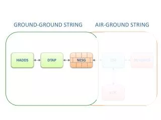
System Diagram SatPC32 RS232 EL - Motor Controller Micro-Controller AZ - Motor Controller Limit Switches Position Encoders 17
Areas of Reasonability Hodge CAD and FEA Torque Calculations/Measurements Ballast Implementation Lyford Sensors and Electrical Motors and Electrical Mechanical Drive Design Schreiber Project Manager Interpolation Implementation Communications Motor Controllers