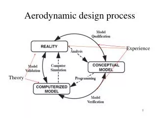
Download
1 / 8
90 likes | 222 Views
Aerodynamic tesing of rear mounted automotive spoilers ( 7/26/2010). Position of Spoiler. Spoiler positions were measured from the top of the model to the top of the spoiler for the Y direction and from the beginning of the slant to the leading edge of the spoiler in the

E N D
Aerodynamic tesing of rear mounted automotive spoilers(7/26/2010)
Position of Spoiler Spoiler positions were measured from the top of the model to the top of the spoiler for the Y direction and from the beginning of the slant to the leading edge of the spoiler in the X direction.
Attached spoiler & Thin Plate • There was no significant change in reduction when position 1 was attached • A thin plate at 5 or 10 deg worked just as well as a spoiler. • The plates used was about 0.02in. thick and 4in long • Continuing experiments with shorter thin plates
Future Tests • Cd with Different slant angles • Flow visualization using white vinyl (on order) and fluorescent oil.
Toyota car model • $4.50 per cubic inch for material • 8in x 8in x 12in sections • Design of sections and attachments