Stability from Nyquist plot
Stability from Nyquist plot. Plot G ( j ω ) for ω > 0 Flip about real axis to get plot of G ( j ω ) for ω < 0 If G(s) has pole(s) on j ω -axis, make a small detour around these pole(s), so that G ( j ω ) is connected Count the #encirclement of –1 by G ( j ω )

Stability from Nyquist plot
E N D
Presentation Transcript
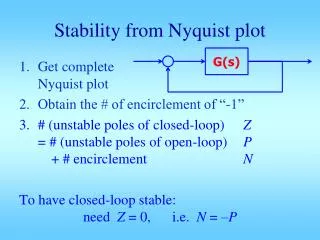
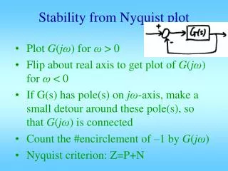
Stability from Nyquist plot • Plot G(jω) for ω > 0 • Flip about real axis to get plot of G(jω) for ω < 0 • If G(s) has pole(s) on jω-axis, make a small detour around these pole(s), so that G(jω) is connected • Count the #encirclement of –1 by G(jω) • Nyquist criterion: Z=P+N
Example: • G(s) stable, P = 0 • G(jω) for ω > 0 as given. • Get G(jω) forω < 0 by conjugating • Connect ω = 0– to ω = 0+.But how?
Choice a) : Where’s “–1” ? # encirclement N = _______ Z = P + N = _______ Make sense? _______ Incorrect
Choice b) : Where is“–1” ? # encir.N = _____ Z = P + N= _______ closed-loopstability _______ Correct
Example: G(s) stable, P = 0 • Get conjugatefor ω < 0 • Connect ω = 0–to ω = 0+.Needs to goone full circlewith radius ∞.
Choice a) : N = 0 Z = P + N = 0 closed-loopstable Incorrect!
Choice b) : N = 2 Z = P + N= 2 Closedloop has two unstable poles Correct!
Example: G(s) has one unstable pole • P = 1, no unstable zeros • Get conjugate • Connectω = 0–to ω = 0+.How?One unstablepole/zeroIf connect in c.c.w.
# encirclement N = ? If “–1” is to the left of A i.e. A > –1 then N = 0 Z = P + N = 1 + 0 = 1 but if a gain is increased, “–1” could be inside, N = –2 Z = P + N = –1 c.c.w. is impossible
If connect c.w.: For A > –1N = ______ Z = P + N = ______ For A < –1N = ______ Z = ______ No contradiction. This is the correct way.
Example: G(s) stable, minimum phase P = 0 G(jω) as given: get conjugate. Connect ω = 0– to ω = 0+,
If A < –1 < 0 :N = ______Z = P + N = ______ stability of c.l. : ______ If B < –1 < A : A=-0.2, B=-4, C=-20N = ______Z = P + N = ______ closed-loop stability: ______ Gain margin: gain can be varied between (-1)/(-0.2) and (-1)/(-4), or can be less than (-1)/(-20)
If C < –1 < B :N = ______Z = P + N = ______ closed-loop stability: ______ If –1 < C :N = ______Z = P + N = ______ closed-loop stability: ______
Open vs Closed Loop Frequency Response And Frequency Domain Specifications C(s) G(s) Goal: 1) Define typical “good” frequency response shape for closed-loop 2) Relate closed-loop freq response shape to step response shape 3) Relate closed-loop freq shape to open-loop freqresponse shape 4) Design C(s) to make C(s)G(s) into “good” shape.
Mr and BW are widely used Closed-loop phase resp. rarely used
Prototype 2nd order system closed-loop frequency response No resonance for z <= 0.7 Mr=0.3dB for z=0.6 Mr=1.2dB for z=0.5 Mr=2.6dB for z=0.4 For small zeta, resonance freq is about wn BW ranges from 0.5wn to 1.5wn For good z range, BW is 0.8~1.25 wn So take BW ≈ wn z=0.1 0.2 0.3 -3dB BW w/wn 0.63 1.58 0.79 1.26
Closed-loop BW to wn ratio BW/wn BW≈wn z
Prototype 2nd order system closed-loop frequency response z=0.1 When z <=0.5 visible resonance peak near w=wn When z >=0.6 no visible resonance peak 0.2 0.3 Since we design for z >=0.5, Mr and wr are of less value No resonance for z <= 0.7 Mr<0.5 dB for z=0.6 Mr=1.2 dB for z=0.5 Mr=2.6 dB for z=0.4 w=wn w/wn
Prototype 2nd order system closed-loop frequency response Mr vs z
Percentage Overshoot in closed-loop step response z > 0.5 is good z
Percentage Overshoot in closed-loop step response Mr < 15% is good, >40% not tolerable Mr
Percentage Overshoot in closed-loop step response Mr < 1 dB is good, >3 dB not tolerable Mr in dB
0.2 z=0.1 0.3 0.4 Open loop frequency response wgc In the range of good zeta, wgc is about 0.7 times wn w/wn
Open-loop wgc to wn ratio wgc≈0.7wn z
In the range of good zeta, PM is about 100*z z=0.1 0.2 0.3 0.4 w/wn
Phase Margin PM = 100z z
Percentage overshoot: Mp PM+Mp =70 line Percentage Overshoot in closed-loop step response Phase Margin in degrees: PM in deg
Important relationships • Closed-loop BW are very close to wn • Open-loop gain cross over wgc ≈ (0.65~0.8)*wn, • When z <= 0.6, wr andwn are close • When z >= 0.7, no resonance • z determines phase margin and Mp: z 0.4 0.5 0.6 0.7 PM 44 53 61 67 deg ≈100z Mp 25 16 10 5 % PM+Mp ≈70
Mid frequency requirements • wgc is critically important • It is approximately equal to closed-loop BW • It is approximately equal town • Hence it determines tr, td directly • PM at wgc controls z • Mp 70 – PM • PM and wgc together controls s and wd • Determines ts, tp • Need wgc at the right frequency, and need sufficient PM at wgc
Low frequency requirements • Low freq gain slope and/or phase determines system type • Height of at low frequency determine error constants Kp, Kv, Ka • Which in turn determine ess • Need low frequency gain plot to have sufficient slope and sufficient height
High frequency requirements • Noise is always present in any system • Noise is rich in high frequency contents • To have better noise immunity, high frequency gain of system must be low • Need loop gain plot to have sufficient slope and sufficiently small value at high frequency
Desired Bode plot shape High low-freq-gain for steady state tracking Low high-freq-gain for noise attenuation Sufficient PM near wgc for stability Ess requirement wgcd w 0dB Noise requirement Mid frequency w 0 -90 PMd -180
Controller design with Bode C(s) Gp(s) From specs: => desired Bode shape of Gol(s) Make Bode plot of Gp(s) Add C(s) to change Bode shape as desired Get closed loop system Run step response, or sinusoidal response Modify controller as needed