Download
1 / 25
250 likes | 704 Views
Developments of the next generation ITS radio communication in Japan. Contents 1. 5.8GHz DSRC in Japan (ARIB STD-T75) 2. Requirements for the next generation ITS radio communication 3. Candidate communication technologies for the next generation ITS radio communications.

E N D
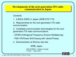
Developments of the next generation ITS radio communication in Japan Contents 1. 5.8GHz DSRC in Japan (ARIB STD-T75) 2. Requirements for the next generation ITS radio communication 3. Candidate communication technologies for the next generation ITS radio communications. - OFDM (Orthogonal Frequency Division Multiplexing) - PSK-VP(Phase Shift Keying with Varied Phase) 4. Demonstration at Shimizu test site ARIB, Japan GSC-8/GRSC-1, Ottawa, Canada 27 April - 1 May, 2003 27 April-1 May, 2003, GSC-8/RAST-1, Ottawa, Canada
Item Europe(CEN) Japan (ARIB STD-T75) North America (ASTM) Radio frequency band 5.8GHz 5.8 - 5.9GHz 5.8GHz Communication system Active Passive Active Data transmission rate Downlink:500kbps Uplink :250kbps Down/Uplink: 3 - 27Mbps Down/Uplink: 1 or 4 Mbps Half-duplex(OBU) Full-duplex (RSU) Half-duplex Duplex Half-duplex 1.1 Regional standards of DSRC 27 April-1 May, 2003, GSC-8/RAST-1, Ottawa, Canada
1.2 ARIB STD-T75 in comparison withRecommendation ITU-R M.1453-1 Item ARIB STD-T75 Rec. ITU-R M.1453-1 - Frequency band 5.8 GHz band 5.8 GHz band - Channel separation 5 MHz 5/10 MHz - Modulation ASK, QPSK ASK, QPSK - Data rate 1 Mbps/ASK 1 Mbps/ASK (Manchester coding) (Manchester coding) 4 Mbps/QPSK 4 Mbps/QPSK (NRZ) (NRZ) - Communication TDMA/FDD TDMA/FDD/TDD - Power supplied to 10m to 30m ≦300mW More than 10m ≦ 300mW RSU antenna Less than 10m ≦10mW Less than 10m ≦10mW - Power supplied to OBU antenna Less than ≦10mW Less than ≦10mW Base station : RSU (Road Side Unit) Mobile station : OBU (On Board Unit) 27 April-1 May, 2003, GSC-8/RAST-1, Ottawa, Canada
1.3 Development of DSRC technologies and applications using ARIB STD-T75 • Smart Gateway by TAO (Telecommunications Advancement Organizations): Development of a radio hand-over technology and a network hand-over technology over consecutive or discrete communication zones. • Smart Communications by the Ministry of Land, Infrastructure and Transport: ITS Communication Services Platform Using 5.8GHz DSRC. • Multiple DSRC Applications Systems at Gas Station by ITS Research Institute: Trial of multi-application DSRC system at Gas station. • Parking Garage Management Systemsby TOYOTA TSUSHO and TOWA Real Estate: Use of DSRC in underground parking garage. 27 April-1 May, 2003, GSC-8/RAST-1, Ottawa, Canada
1.4 Nationwide ETC Deployment(ETC using ARIB T-75 DSRC standard) 27 April-1 May, 2003, GSC-8/RAST-1, Ottawa, Canada
1994, Question on ITS Recommendations (Answers to the Question) 2001 1997 1998 2000 1995 1996 ITU-R/SG8/WP8A/WG2: Standardization for ITS Objectives & Requirements Rec. ITU-R M. 1310 Functionalities Rec. ITU-R M. 1451 Current Use Radio services - Broadcast - DSRC - Short-range radar - Short-range vehicle-to-vehicle - Short-range continuous - Wide area of Spectrum Traffic & Spectrum Requirements Short-range Radar Rec. ITU-R M. 1452* 5.8GHz DSRC Rec. ITU-R M. 1453 ? VICS(DSRC) Technologies ? ? Next generation ITS radio communication * Rec. ITU-R M. 1453, Revised in 2002. 2.1 ITS Standardization in ITU-R“What is the next generation ITS radio communication?” 27 April-1 May, 2003, GSC-8/RAST-1, Ottawa, Canada
ARIB STD-T75 generally satisfies the requirement except for the very small area shown below. - high data rate high-speed traveling; Continuous communication - Very high data rate semi-stationary; Broadband ITS Radiocommunication(Resolution RAST 10/7) Allowable Information supply-type traveling speed (high-speed traveling) (mobility) [Km/h] 180 Information supply-type (high-speed travelling) 100 Information supply-type Image of a new Specific region (semi-stationary) portable telephone entry charging Parking lot 20 Logistic Management Drive-through Filling Pedestrian station support Video/music distribution On-demand Convenience store information Connection to Internet (IP) Data transmission 0 rate 100 K 1 M 10 M [bps] 2.2 Data transmission rate requirement for the next generation ITS radio communication 27 April-1 May, 2003, GSC-8/RAST-1, Ottawa, Canada
*The road-vehicle communications technology group in the study group for ”Efficient Use of the Radio Spectrumfor ITS” 2.3 Development status in ARIB* for the next generation ITS radio communication 27 April-1 May, 2003, GSC-8/RAST-1, Ottawa, Canada
Delayed wave 1 Direct wave Delayed wave 2 Multi-path fading 2.4 Countermeasures to Multipath fading 27 April-1 May, 2003, GSC-8/RAST-1, Ottawa, Canada
Technologies to realize reception from multiple antennas Shadowing Avoidance of shadowing by reception from multiple Antennas 2.5Countermeasures to Shadowing 27 April-1 May, 2003, GSC-8/RAST-1, Ottawa, Canada
An impractical fast hand-over is required for the discrete frequency system Hand-over per 1 to 2 seconds (30-60m zone, 100km/h) f f f f f f f f f f f 1 2 3 1 2 3 1 2 3 1 2 Hand-over Hand-over repetition can be reduced for the same frequency system Hand-over per several seconds (30-60m zone, 100km/h) No hand-over No hand-over f f f f f f f f f f f 1 1 1 1 1 1 2 2 2 2 2 Hand-over Features of Single Frequency Network are- Efficient usage of frequency resources (Fewer channels)- Measures against shadowing and multi path fading through path diversity- No hand-over or easy hand-over 2.6Continuous communication (An example of Single Frequency Network) 27 April-1 May, 2003, GSC-8/RAST-1, Ottawa, Canada
- Concept of OFDM modulation scheme Features of OFDM - Robustness against frequency selective fading (Narrow subcarrier) - High spectrum efficiency (Minimum carrier frequency spacing) - Low Inter Symbol Interference (ISI) and Inter Carrier Interference (ICI): (Provision of Guard Interval) - Anti-Multipath mechanism of OFDM Direct wave Delayed wave Guard interval Direct wave Symbol A Symbol B Symbol C Delayed wave Symbol A Symbol C Time Symbol B Guard interval Delay time Reduced ISI and ICI 3.1 Modulation scheme and features of OFDM 27 April-1 May, 2003, GSC-8/RAST-1, Ottawa, Canada
- Parameters of the system Features of the system - Seamless hand-over on single radio frequency by dividing the sub-carrier - Time interleave within the slot to compensate for time variation of the received signal - High mobility through adoption of differential PSK without pilot carriers Note; RLAN devices are generally not designed to be used at automotive or higher speeds. - Comparison with IEEE 802.11a 3.2 Features of the developed OFDM systems 27 April-1 May, 2003, GSC-8/RAST-1, Ottawa, Canada
Channel No.1 Channel No.2 f Divide subcarrier into two groups 3.3 Hand-over on Single radio frequency by dividing the subcarrier (OFDM) Mechanism of high speed hand-over on single radio frequency - The roadside transmitter transmits subcarrier groups arranged in frequency domain - The roadside transmitters in a data zone simulcast the identical data to reduce shadowing effects - All roadside transmitters are synchronized - When a vehicle passes a boundary between data zones, the receiver demodulates the signal of the two data zones, and extracts suitable data zones (Handover) 27 April-1 May, 2003, GSC-8/RAST-1, Ottawa, Canada
3.4 System performance simulation (OFDM) - Power spectrum(6dB Back-off, Class AB) - Carrier to Interference Ratio (CIR) Required BER=10-5 CIR=8dB for static two waves interference CIR=13dB for Rice type(k=6dB) interference - Error rateunder Rice (k=6dB) type multipath interference, after error correction Maximum Doppler frequency=966Hz < < 64,000Hz (Subcarrier spacing)at vehicle speed of 180km/h Parameters are as per listed on the slide No. 3.2 Delay difference=122ns Delay difference=488ns 27 April-1 May, 2003, GSC-8/RAST-1, Ottawa, Canada
- Concept of PSK-VP (Phase Shift Keying with Varied Phase) An anti-multipath scheme by imposing phase-variation on the symbol of PSK cf. IEEE Trans. VT-42, No.4, pp. 625-640 IEEE Trans. VT-42, No.2, pp. 177-185 ITST2001 Proc., S3-3, pp. 625-639 - Configuration 3.5 PSK-VP Modulation scheme 27 April-1 May, 2003, GSC-8/RAST-1, Ottawa, Canada
Total cancel over the effective area occurs when phase difference aapproaches p. No complete cancel over the effective area 3.6 Anti-Multipath mechanism of PSK-VP - Principle of Anti-Multipath Feature No complete cancel in multipath by imposed phase-variation, i.e., the survivor somewhere exists. Implicit RAKE / Path-Diversity - Improvement Example in Two-Wave Model i) Vector Diagram for Conventional PSK ii) Vector Diagram for PSK-VP 27 April-1 May, 2003, GSC-8/RAST-1, Ottawa, Canada
3.5 Performance Comparison in Two-Ray Multipath (PSK-VP) Condition: ・Two waves with a same mean power ・Each wave subject to Rayleigh fading cf. IEEE Trans. VT-42, p. 179 - Remarkable BER improvement within 0.8-symbol delay difference - Appropriate delay differences encourage path-diversity effect and improve BER even better than non-diversity case in non-selective fading. 27 April-1 May, 2003, GSC-8/RAST-1, Ottawa, Canada
3.8 Feature of PSK-VP in DSRC Application - Applicable to simultaneous transmission in the downlink by anti-multipath feature - Robust for rapid fading by no adaptation process and highly-maintained symbol-rate - Simple structure without large-scale circuit like equalizer or FFT - Easy extension from existing PSK-based standard(e.g. ARIB STD-T75) Multimode by swapping waveform tables / A common detector applies to PSK and PSK-VP Proto-Modem Example Triple mode (QPSK-VP/QPSK/ASK) transceiver baseband is easily implemented into single FPGA chip. 27 April-1 May, 2003, GSC-8/RAST-1, Ottawa, Canada
4.1 Outlines of demonstration at the Shimizu test courseconducted in 19th to 21st February, 2003 ERP ; Electronic Road Pricing Vehicle to vehicle communication ARIB test building ERP entry ERP exit OFDM Frequency sharing ASK/QPSK-T75 Radio propagation QPSK-VP In vehicle LAN In doortests Shimizu ITS test site Demonstration items 1. Frequency sharing technology 2. Continuous road vehicle communication technology 3. Radio propagation model 4. Coordination of road-vehicle and vehicle-vehicle communication 5. Connectivity between road vehicle communication and vehicle LAN 6. Vehicle detection and identification for Electronic Road Pricing 27 April-1 May, 2003, GSC-8/RAST-1, Ottawa, Canada
Data- RX data Combiner DET DET DET QPSK-VP TX data Modulator RFU RFU RFU BSU -1 -2 -n CRC QPSK TX or MOD data BCH Coder DET RX data OBU Radio Area Size typ. 30-50mx n Channel Spacing 5 MHz Downlink p/4 - QPSK-VP (3.072Mbps) + ARIB STD-T75 Higher Layer Uplink p/4 - QPSK (4.096Mbps) +BCH(63,51) ARIB STD-T75 in conformity to 4.2 Extension of ARIB STD-T75 with PSK-VP Scheme - Basic Structure and Specification cf. ITST2002 Proc., S7-1, pp.233-237 ITST2002 Proc., S7-2, pp.239-244 - Downlink (Road to Vehicle) Simultaneous transmission using path-diversity effect of PSK-VP Main Specification - Uplink (Vehicle to Road) Site-diversity using bit-error based data-combining scheme 27 April-1 May, 2003, GSC-8/RAST-1, Ottawa, Canada
Error ! QPSK (STD-T75) QPSK (STD-T75) + Data-Combining 50 1 BER -5 Error Free 10 30 -10 10 QPSK-VP 1 10 Starting Point Error Free -5 10 -10 -10 10 Rx Level(dBm) BER BER -30 -50 -70 -90 187.5 250.0 0.0 62.5 125.0 Distance(m) ▲: Position of Roadside Antenna 4.3 Field verification for Continuous Communication without Hand-over (PSK-VP) - Downlink (Road to Vehicle) - Uplink (Vehicle to Road) ▲: Position of Roadside Antenna 27 April-1 May, 2003, GSC-8/RAST-1, Ottawa, Canada
RFU1 13.0 13.0 ° ° Roadside Antenna 0.7m 0.7m OBU Antenna Position Obstacle (Truck) 11.0m 11.0m Traveling Direction -40 -40 大型トラック Large Truck 7.1m 7.1m 4.9m 4.9m Vehicle with OBU 1.2m 1.2m -60 -60 13.0 13.0 ° ° RX Level [dBm] RFU2 55m 55m 40m 40m End Point Start Point -80 -80 62m 62m -100 -100 0 5 10 15 0 5 10 15 Shadowing area 測定経過時間(秒) 1 Shadowing area BER -5 1 10 BER -5 10 -10 10 -10 10 RX Level [dBm] Time [s] Time [s] 4.4 Field verification for Anti-Shadowing Effect (PSK-VP) Traveling Line of Right Side of Large Truck RFU2 RFU1 ◇ Single Transmission from RFU2 ◇ Simultaneous Transmission from RFU1&2 27 April-1 May, 2003, GSC-8/RAST-1, Ottawa, Canada
4.4 Field Verification for realization of long radio areaby Transmission Diversity (PSK-VP) Vehicle Speed: 120km/h - Simultaneous Transmission from Both Antennas - Single Transmission from Upper Antenna Roadside Antenna Setup from Lower Antenna 27 April-1 May, 2003, GSC-8/RAST-1, Ottawa, Canada
RSE1 RSE 2 RSE 3 RSE 4 A C C C Divided Channel No.1 Divided Channel No.2 B B B D Frequency Error free during hand-offs - RSE Communication range: 30m - RSE Antenna height: 10m 4.5 An example of seamless hand-over (OFDM) 27 April-1 May, 2003, GSC-8/RAST-1, Ottawa, Canada