Sequential Testing and Scan Flip-Flop Techniques
Learn about sequential testing challenges, scan flip-flops, LSSD, and testing enable techniques to enhance circuit reliability and performance. Discover how sequential redundancy and detectability influence test pattern generation methods.

Sequential Testing and Scan Flip-Flop Techniques
E N D
Presentation Transcript
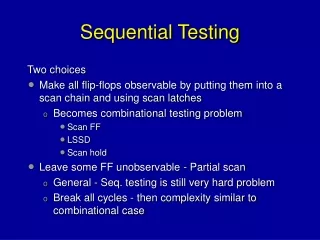
Sequential Testing Two choices • Make all flip-flops observable by putting them into a scan chain and using scan latches • Becomes combinational testing problem • Scan FF • LSSD • Scan hold • Leave some FF unobservable - Partial scan • General - Seq. testing is still very hard problem • Break all cycles - then complexity similar to combinational case
Master Slave Data Q Q Clock Scan chain Scan Flip-Flop Test enable Adds extra logic and delay in data paths Scan data Multiplexor ts+t’d data
LSSD (Level Sensitive Scan Design) Latch Scan chain Master Slave Data • Does not introduce delay in data path • Overhead is 2 ANDs and Invertor • When master clock is working, test clock is 0 and vice-versa Q Q Master clock Slave Clock Scan Data Test clock
Scan-Hold Flip-Flop (SHFF) To SD of next SHFF D • The control input HOLD keeps the output steady at previous state of flip-flop. • Applications: • Reduce power dissipation during scan • Isolate asynchronous parts during scan test • Delay testing Q SD SFF TE Q CK HOLD
Relevant Results • Theorem: A cycle-free circuit is always initializable. It is also initializable in the presence of any non-flip-flop fault. • Theorem: Any non-flip-flop fault in a cycle-free circuit can be detected by at most dseq + 1 vectors where dseq is the sequential depth of the circuit. • General ATPG complexity: To determine that a fault is untestable in a cyclic circuit, an ATPG program using nine-valued logic may have to analyze 9Nff time-frames, where Nff is the number of flip-flops in the circuit.
Partial-Scan Methods Partial Scan: make only some of the flip-flops scan • Eliminate all cycles • Select a minimal set of flip-flops for scan to eliminate all cycles (saves area and makes it a lot easier to test). • Eliminate some cycles • Alternatively, to keep the overhead low only long cycles may be eliminated. • In some circuits with a large number of self-loops, all cycles except self-loops may be eliminated. It has been shown empirically that this lowers the complexity of ATPG considerably.
Sequential Automatic Test Pattern Generation (ATPG) Tutorial and Survey Paper: Gate-Level Test Generation for Sequential Circuits KWANG-TING CHENG University of California, Santa Barbara
Iterative array model Unroll FSM N time frames and treat as one combinational module
Five valued logic - example Not allowed to specify value at latch boundary Values are This would imply that the fault is not testable However,…
Nine valued logic To propagate the fault effect from primary input a to the output of gate g1 in time-frame 1, the only requirement is that the other input of g1 have a 0 for the fault-free circuit (there is no value requirement at this signal for the faulty circuit). Nine values are 0/0 0/1 0/x 1/0 1/1 1/x x/0 x/1 x/x We conclude that sequence ab = (00 01) is a test sequence
Finding sequentially undetectable faults • Unroll the circuit a specified number of time frames • Assume that the present state lines in the first time frame are fully controllable • Assume that the next state lines in the last time frame are fully observable. • Use combinational test pattern generator • Two different procedures • Fault occurs only in the last time frame • Fault occurs in all time frames • In either case, lack of combinational test implies that fault is sequentially undetectable
Undetectability and redundancy Redundancy is associated with I/O behavior of circuit and undetectability is associated with the test generation procedure used. • A fault is called undetectable if no input sequence can produce a fault effect (D or D-bar) at any primary output • A fault is redundant if the presence of the fault does not change the input/output behavior of the circuit. • For a complete combinational test generator, redundancy and undetectability are equivalent. • (not so for sequential behavior)
Detectability under - • Full-scan • Combinationally undetectable (equal to redundant) • Reset • input sequence exists where the PO output responses of the good and faulty circuits differ, both starting from the reset state. • Hardware reset is not available (reset sequence) • Single observation time (SOT) • Sequence exists where fault effect appears at the same time and at the same output independent of the power-up state. • Multiple observations times (MOT) • Sequence exists where fault effect appears, but time and place of fault effect depends on power-up state.
Example - SOT undetectable and MOT detectable Sequence AC = (11,01) detects fault but at different times depending on initial state of FF. • If initial state is X/0, output will be 1/0 for first vector • If initial state is X/1, output will be 1/1 for first vector and 0/1 for the second vector.
Sequential redundancy A fault is sequentially redundant under a mode of operation if the fault does not change the expected output sequence under that mode Modes: • Reset mode (hardware reset to a reset state) • Synchronization mode (after the reset sequence, the output sequences do not change. Can wait K cycles before looking at the outputs) • No-synchronization mode (no matter which state the machine starts in, for that state the output sequences do not change, i.e. can’t change the behavior of any state. Must hold for all sequences starting from t=0.)
Partial test under 1. synchronization and 2. no-synchronizations • A partial test under a mode is an input sequence which distinguishes the good and faulty circuit • After the synchronizing sequence • Assuming that the good and faulty circuits power up in the same initial state. • A fault is sequentially redundant (under a mode) if and only if there is no partial test.
Partial test • (b) is STG of good machine, (c) is STG of machine with fault where cube is stuck at 0. • Sequence 011 initializes good machine to 11. • However faulty machine if powered up in 00 can not be initialized. • Fault is partially detectable if powered up in 00, otherwise not detectable. Thus fault is partially detectable.
Assuming a reset state STALLION (Ma,…, STEED (Devadas,…), VERITAS (Cho, Hachtel, …) Preprocessing phase: find the set of reachable states and for each, the shortest transfer sequence from the initial state. (Veritas uses BDDs) Test generation phase: • Iterated array is constructed (variable number of time steps?) • Combinational test for array is generated first where present state is restricted to reachable states. This provides propagation sequence to a PO. • State transfer justification sequence is looked up from preprocessed data (how to get from initial state to test state). • Justification and propagation sequences derived from good machine (may not be valid for faulty machine). • Fault simulation is used to check this. If not valid, then alternate (shorter) sequence can be generated.
Computing reset sequences • Synchronizing (reset) sequence drives the circuit to a fixed known state. (may be corrupted by fault so needs to be simulated) • Deciding if a design is resetable can be done without deriving a reset sequence • If resetable, reset sequence can be generated heuristically
Equivalence • Normal notion: If a machine has a given reset state, then two machines are said to be equivalent if there reset states are equivalent (i.e. starting from these two states the I/O behavior is the same • However, there may be no reset state and the machine may power up in any state. What do we mean by equivalence then?
Fundamental alignment theorem, Pixley[1990] Definitions: • States s1,s2 of machines, D1 and D2, are: • equivalent if there is no distinguishing sequence where D1 start in s1, and D2 starts in s2 . We denote this as s1 ~ s2. • alignable if there exists a input sequence S such that S(s1) ~ S(s2) . Then we say that s1 s2 • Definition: Two machines D1 and D2 are equivalent iff Fundamental Theorem: • Two machines are equivalent iff there exists a universal aligning sequence, i.e. a single sequence that aligns all pairs.
Proof • Let where ESP is the set of equivalent state pairs. Let F(P) be an input sequence which maps at least one into ESP, i.e. • Define Then • Then • Then aligning sequence is where and and n is where
Self equivalence • A state s0 is a reset state if there exists a sequence S such that for any state s S(s) ~ s0. • A design is resetable if it has a reset state. • A machine may not be equivalent to itself if it is not resetable. • D1 and D2 are equivalent iff all state pairs are alignable.