Download
1 / 62
620 likes | 648 Views
Explore object interaction, collaboration, CRC cards, and modeling using communication and timing diagrams in object-oriented systems. Enhance software modularity and system resilience through appropriate distribution of object responsibilities.

E N D
CSE323การวิเคราะห์และออกแบบระบบ (Systems Analysis and Design) Lecture 07: Object Interaction and Specifying Operations
Object Interaction – Communication Diagrams & Interaction Overview DiagramsTiming Diagrams Based on Chapter 9 of Bennett, McRobb and Farmer: Object Oriented Systems Analysis and Design Using UML, (3rd Edition), McGraw Hill, 2005.
In This Lecture You Will Learn: • Object Interaction and Collaboration • CRC Cards • how to model object interaction using an interaction communication diagram. • how to model interactions using interaction overview diagrams; • how to model interaction using an interaction sequence diagram; • how to use timing diagrams.
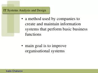
Object Interaction & Collaboration • Message Passing • Objects communicate by sending messages • When an object sends a message to another object, an operation is invoked in the receiving object • The aim of modelling object interaction is to determine the most appropriate scheme of message passing between objects to support a particular user requirement
Object Interaction & Collaboration • Appropriate distribution of object responsibility improves software modularity • Each class tends not to be unduly complex, and as a result is easier to develop, to test and to maintain. • Each class is relatively small and self-contained, and as a result has a much greater potential for reuse. • The system is more resilient to changes in its requirements • A modular system is easier • to be maintained and upgraded • to achieve high reliability • to be implemented in small, manageable increments
CRC Cards • Class–Responsibility–Collaboration (CRC) cards help to model interaction between objects • Brainstorm the classes • Allocate each class to a team members • For each use case, role play the interaction to distribute responsibilities among classes: • each objectidentifies the object that he/she thinks is most appropriate to take on a needed responsibility for collaboration • each objectshould be as lazy as possible, refusing to take on any responsibility unless persuaded by its fellow objects
Class Name: Responsibilities Collaborations Collaborations with other classes are listed here, together with a brief description of the purpose of the collaboration. Responsibilities of a class are listed in this section. CRC Cards
Dynamic Analysis with UML • Communication Diagrams • Sequence Diagrams • Interaction Overview Diagrams • Timing Diagrams In UML 1.x, communication diagrams are called collaboration diagrams. In UML 1.x, interaction overview diagrams and timing diagrams do not exist.
Communication Diagrams • Hold the same information as sequence diagrams. • Show links between objects that participate in the collaboration. • No time dimension, sequence is captured with sequence numbers. • Sequence numbers are written in a nested style (for example, 3.1 and 3.1.1) to indicate the nesting of control within the interaction that is being modelled.
:Campaign anAdvert:Advert getCost Communication Diagrams • Notations • Message order is captured with sequence numbers, which are written in a nested style (for example, 3.1 and 3.1.1) to indicate the nesting of control within the interaction that is being modelled. currentAdvertCost = anAdvert.getCost()
Sequence Diagrams • Purpose • A sequence diagram shows an interaction between objects arranged in a time sequence. • Sequence diagrams can be drawn at different levels of detail and to meet different purposes at several stages in the development life cycle. • Sequence diagrams are typically used to represent the detailed object interaction that occurs for one use case or for one operation.
Sequence Diagrams • Notations • Objects (or subsystems or other connectable objects) involved in interaction appear horizontally across the page and are represented by lifelines. • The execution or activation of an operation is shown by a rectangle on the relevant lifeline.
Sequence Diagrams • Notations • Messages are usually shown by a solid horizontal arrow. • A synchronous message or procedural call is shown with a full arrowhead, causes the invoking operation to suspend execution until the focus of control has been returned to it. • It is optional to show reply messages(with dashed arrows) because it can be assumed that control is returned to the originating object at the end of the activation in a destination object (except for asynchronous messages). • A reflexive message that an object sends to itself is shown by a message arrow that starts and finishes at the same object lifeline.
Sequence Diagrams • Combined Fragments • Sequence • Vertical dimension shows time. • Iteration (looping)is shown by a combined fragment rectangle with the interaction operator ‘loop’. • The loop combined fragment only executes if the guard condition in the interaction constraint evaluates as true. • Selection (branching)is shown by a combined fragment rectangle with the interaction operator ‘alt’ (a short form of alternatives). • The alt combined fragment has two (or more) compartments known as operands. Each operand corresponds to one of the alternatives in the combined fragment and each operand should have an interaction constraint to indicate under what conditions it executes.
Sequence Diagrams • Notations • Object creation is shown with the construction message (dashedarrow) going to the object symbol. • Object destruction is indicated by a large X on the lifeline on the destruction point.
Interaction Overview Diagrams • Variants of activity diagrams • Focuses on the flow of control in an interaction • Nodes in the diagram may be interactions or interaction occurrences • Interaction needs to be broken down into its key elements.
Interaction Overview Diagrams • An alternative version of the sequence diagram Add a new advert to a campaign if within budget is shown on the next slide and is used to develop an interaction overview diagram
sd Add a new advert to a campaign if within budget :CampaignManager :Client :Campaign :Advert getName listCampaigns ref List client campaigns ref Get campaign budget addCostedAdvert alt [totalCost <= budget] ref Create advert [else] ref Create request
Interaction Fragment Used sd Get campaign budget :CampaignManager :Campaign :Advert checkCampaignBudget loop [For all campaign’s adverts] getCost getOverheads
sd Create advert :Campaign :Advert Advert newAd:Advert Interaction Fragment Used
sd Create request :Campaign :Advert Request newRequest:Request Interaction Fragment Used
sd Add a new advert to a campaign if within budget sd List Campaigns for Client :CampaignManager :Client :Campaign getName listCampaigns loop [For all client’s campaigns] getCampaignDetails Initial node ref Get campaign budget Interaction occurrence In-line sequence diagram sd Add costed advert :Campaign :CampaignManager addCostedAdvert Decision [totalCost > budget] [totalCost <= budget] ref ref Create advert Create request Final node
Timing Diagrams • A new feature in UML 2.0 • Show how time constraints affect interactions between lifelines • The sequence diagram Car enters car park is the basis for the subsequent timing diagram
sd Car enters car park :Barrier after:WeightSensor before:WeightSensor activate :TicketMachine Active ticketRequested raiseBarrier deactivate lowerBarrier barrierLowered Lowered Lowered Blocked Inactive Raised Timing Diagrams
Timing Diagrams Sloped line represents duration of state change sd Car enters car park lifelines :Barrier, :TicketMachine Diagram has two instances, one for each lifeline Timing Constraint {t..t+3s} Raised :Barrier Lowered barrierLowered Blocked raiseBarrier :TicketMachine Active Message from one lifeline to another Inactive t
Model Consistency • Timing diagrams must be consistent with the relevant sequence diagrams and state machines.
Summary In this lecture you have learned about: • how to model object interaction using an interaction communication diagram. • how to model interactions using interaction overview diagrams; • how to model interaction using an interaction sequence diagram; • how to use timing diagrams.
OBJECTIVES To understand : • why operations need to be specified • The difference between algorithmic and non – algorithmic methods • How to interpret different ways of specifying operations • How to specify operations using one method.
In this chapter you will learn : • How to use : - Decision Tables - Pre and post-condition pairs - Structured English - Activity Diagrams - Object Constraint Language
Why we specify operations • From analysis perspective : - Ensure user needs are understood • From design perspective : - Guide programmer to an appropriate implementation (i.e. method) • From test perspective : - verify that the method does what was originally intended
Types of Operation and Their effects • Operations with side-effects may: - Create or destroy object instances - Set attribute values - Form or break links with other objects - Carry out calculations - Send messages or events to other objects - Any combination of these • Operations without side-effects are pure queries - Request data but do not change anything
Services Among Objects • When objects collaborate one object typically provides a service to another • Examples : - A client object might ask a campaign - Structured English - Activity Diagrams - Object Constraint Language
Contracts: an approach to defining services • A service can be defined as a contract between the participating objects • Contracts focus on inputs and outputs • Intervening process is seen as a black box • Irrelevant details are hidden • This emphasizes service delivery, and ignores implementation
Contract-Style Operation Specification : • Intent or purpose of the operation • Operation signature, including return type • Description of the logic • Other operations called • Events transmitted to other objects • Any attributes set • Response to exceptions (e.g. an invalid parameter) • Non-functional requirements
Types of Logic Specification • Logic description is probably the most important element. • Two main categories: • Algorithmic types are white box – they focus on how the operation might work • Non-algorithmic types are black box – they focus on what the operation should achieve.
Non-Algorithmic Techniques • Appropriate where correct result matters more than method to arrive at it • Decision tree: complex decisions, multiple criteria and steps (not described further here) • Decision table: similar applications to decision tree • Pre- and Post-condition pairs: suitable where precise logic is unimportant or uncertain
Rule 3 Conditions and actions Rule 1 Rule 2 Conditions Is budget likely to be overspent? N Y Y Is overspend likely to exceed 2%? - N Y Actions No action X Send letter X X Set up meeting X Example Decision Table
Algorithmic Techniques • Suitable where users understand the procedure for arriving at a result • Can be constructed top-down, to handle arbitrarily complex functionality • Examples: - Structured English - Activity Diagrams
Structured English : • Commonly used, easy to learn • Three types of control structure, derived from structured programming: - Sequences of instructions - Selection of alternative instructions (or groups of instructions) - Iteration (repetition) of instructions (or groups of instructions)
Sequence in Structured English • Each instruction executed in turn, one after another get client contact name sale cost = item cost * ( 1 - discount rate ) calculate total bonus description = new description
Selection in Structured English • One or other alternative course is followed, depending on result of a test : if client contact is ‘A’ set discount rate to 5% else set discount rate to 2% end if
Iteration in Structured English • Instruction or block of instructions is repeated - can be a set number of repeats - or until some test is satisfied, for example do while there are more staff in the list calculate staff bonus store bonus amount end do
Activity diagram • Are part of UML notation set • Can be used for operation logic specification, among many other uses • Are easy to learn and understand • Have the immediacy of graphical notation • Bear some resemblance to old-fashioned flowchart technique