Touchpad-Controlled Parametric Equalizer
This project presents a novel touchpad-controlled parametric equalizer designed for real-time audio filtering, targeted at musicians and sound engineers. The system allows for independent control over filter parameters such as center frequency, bandwidth, and gain using an intuitive touch interface. An RS-232 connection facilitates communication with the DSP-implemented algorithm, ensuring real-time audio processing. By employing pressure-sensitive sensors and advanced positioning algorithms, the equalizer provides greater flexibility and efficiency compared to traditional control methods like sliders and knobs.

Touchpad-Controlled Parametric Equalizer
E N D
Presentation Transcript
Touchpad-ControlledParametric Equalizer ECE 445 Group #24 Anthony Mangognia Alexander Spektor Farsheed Hamidi-Toosi TA: Chad Carlson
Introduction • Goal: To create a real-time audio filtering solution for musicians and sound engineers • Goal: To provide independent control over filter parameters: center frequency, bandwidth, and gain • Goal: To create a geometrically-intuitive input device for the filter
Existing Alternatives • X-Band Equalizers • Sliders or knobs • Limited control • Takes time to adjust • Discrete frequency bands • Digital Parametric Equalizers • Pseudo-continuous frequency sweep • Cumbersome software-based control
Design Overview • Input Device: Pressure-sensitive touchpad. • Horizontal position: center frequency • Vertical position: gain • Overall Pressure: bandwidth • Input-Filter Interface: RS-232 serial connection • Filter: DSP-implemented algorithm • Second-order IIR filter (based on Mitra-Regalia topology) • Filter coefficients update in real-time
Design Block Diagram Audio In DSP: Parametric Equalizer Filter Microcontroller: Positioning Algorithm & Touchpad DSP interface Audio Out Touchpad
1. Touchpad Process Pressure Sensor Voltage Differential Bias cancellation/Tuning Circuit 830x Amplifier PIC A/D
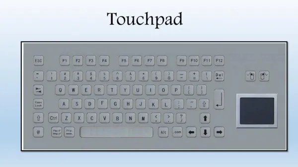
Touchpad • Four corner-mounted pressure sensors on height-adjustable shelves • Pressure sensor output voltage varies with finger position • Positioning algorithm • Surface much larger than typical commercially-available touchpads
Touchpad Design Touchpad Surface Sensor Mount Pressure Sensors Slide-in touchpad Bird’s Eye View Height-adjustable sensor mount Sensor Mount
Pressure Sensors • Honeywell 125PC30G1 • Pressure range: 0-30 psi • Sensitivity: 8.33mV/psi V- GND V+ +10 Amplifier
Touchpad Signal Amplification • Instrumentation Amplifier: AD622AN • Low-cost: $4.90 • Gain: 2-1000x, external resistor control • 56Ω 830x gain • Easy integration: wide power supply voltage gain (±2.6V-±15V) • Large gain Large bias voltage • Solved with 1MΩ pull-down resistors at inputs and 100k potentiometer (calibration)
2. Microcontroller-EnabledTouchpad DSP Interface Four sensor A/D Positioning Algorithm Serial Transmission
Analog to Digital Conversion • 8-bit A/D conversion for quicker calculations • 10-bit possible for PIC16F877A, but doubles number of bytes for mathematical operations • Decreases resolution to 256 points maximum • More than enough to simulate continuous operation • Read 8 values for each sensor and average • Functions as a digital LPF
Positioning Algorithm Sensor 1: V1 (0, Ymax) X2 = V2 Xmax / (V2 + V1) Sensor 2: V2 (Xmax, Ymax) Touchpad Surface Y1 = V1 Ymax / (V1 + V0) Y2 = V2 Ymax / (V2 + V3) (X,Y) – Finger Position Sensor 3: V3 (Xmax, 0) Sensor 0: V0 (0, 0) X1 = V3 Xmax / (V3 + V0)
Positioning Algorithm Sensor 1: V1 (0, Ymax) X2 Sensor 2: V2 (Xmax, Ymax) Touchpad Surface Y1 (Xavg,Yavg) – Average Y2 Sensor 3: V3 (Xmax, 0) Sensor 0: V0 (0, 0) X1
Positioning Algorithm Sensor 1: V1 (0, Ymax) Sensor 2: V2 (Xmax, Ymax) X’ = X1 (Ymax-Yavg) + X2 (Yavg) Touchpad Surface (X’,Y’) – Weighted Average Y’ = Y1 (Xmax-Xavg) + Y2 (Xavg) Sensor 3: V3 (Xmax, 0) Sensor 0: V0 (0, 0)
Data Sent to DSP • Three-byte start sequence: “230” x3 • Four sensor readings: S0, S1, S2, S3 • Two one-byte positioning words (x3) • One three-byte stop sequence: “232” x3 230 230 230 S0 S1 S2 S3 X X X Y Y Y 232 232 232
Serial Data Transmission • Data transmitted at 38400kbps • Default rate for DSP • Data Format • Sent over standard serial cable • DB-9 connector 1 START BIT 8 BIT WORD 1 STOP BIT
RS-232: Voltage Level Conversion • PIC output at TTL levels • ~ 0 - 5V • DSP input at RS-232 levels • ~ ±12V swing • Conversion with MAX232 line driver 38400kbps serial data at TTL from PIC MAX232 Line Driver 38400kpbs serial data at RS-232 to DSP
3. DSP: Audio Filtering Receive/Decode Data from Touchpad Update Filter Coefficients Apply Filter to Audio Input and Send to Speakers
Filter Design • Based on Mitra-Regalia second-order IIR • Design Equations: • β = – cos(ωc) • k = 10(GAIN/20 dB) • α = (1 – tan (BW/2) (1 + tan (BW/2) • Programmed in C for TI-54x fixed-point DSP A(z) = All-Pass Lattice Mitra-Regalia Topology
Src: Montana University Web site. http://www.coe.montana.edu/ee/rmaher/ECEN4002/lab4_020226.pdf
Design Challenges: Touchpad • Pressure sensor noise • Problem: 30mV peak-to-peak noise level • Solution: 8-point averaging filter after PIC A/D • PIC A/D crosstalk • Problem: Changes in one pressure sensor affected values read for other • Solution: Pull-down 0.1μF capacitors at A/D input pins • Serial communication pins • Problem: PICPC communication and PICDSP communication use different DB-9 transmit pins • Solution: Internal rewiring to accommodate both
Design Challenges: Filter • Filter type change • Problem: Original algorithm (Chamberlin) produced undesirable resonance frequencies • Solution: Switched to Mitra-Regalia topology • IIR Instability • Problem: Direct form two implementation caused overflow • Solution: Implemented lattice structure to reduce overflow • Quantization • Problem: Fixed-point quantization of coefficients • Solution: Lattice structure ensures pole-zero cancellation
Internal Component Test • Pressure Sensor + Amplifier • Unwanted signal oscillation: 60mV peak to peak • Due to conflicting RC networks • Too high for 1V sampling range • Solution: Removed analog smoothing filter
Finished Product Test • Amplitude test performed with oscilloscope • Input: 11 kHz Sine Wave, 200 mV peak-to-peak • Tests: gain = 2 and gain = .5 at 11kHz by measuring peak-to-peak voltage of output using the scope • Amplitude resolution is .24 dB from -6dB to 6dB • Exceeded design requirement which stated 2-3 dB amplitude resolution
Finished Product Test • Frequency tests performed with scope • Fix bandwidth, set gain = 2 • Inputs: Sine at set frequencies, Gaussian White Noise • Using FFT on scope, can see if frequencies boosted by 2x at desired center frequency • Proposed frequency resolution: 1 Hz (not necessary) • Total of 200 center frequencies possible, distributed them logarithmically since hearing is logarithmic • High resolution for low frequencies, less resolution for higher frequencies • Results: Filter works for all frequencies within hearing range (20Hz-20kHz)
Finished Product Test • Bandwidth Tests • As total pressure increases, increase bandwidth • Tested using FFT on scope • Input signals: Gaussian white noise, music • Test to see if bandwidth varies from 50Hz to 22050Hz as pressure increases • Passed tests, including aural tests
Finished Product Test • Latency Tests • The target of less than 100ms system latency was achieved • Delay due to pressure sensors negligible • Delay due to PIC negligible (assembly code minimized cycles) • DSP initially had some latency, but code was optimized by eliminating FOR loops (less than 30000 cycles at ~MHz) • Usability tests confirm that system latency is not an issue when using this system, negligible
Finished Product Test • Usability Tests and Conclusions • Tested on music signals and white noise signals • Qualitative analysis: • Was the filtering audible? • Did the touchpad respond as desired? • How intuitive was it to “find” a desired frequency? • Is this design marketable? If so, why? • How much would this cost to manufacture?
Final Thoughts • Improvement: Better pressure sensors • Higher output voltage Less amplification • Improvement: Cascade feature • A button to keep current settings and use new settings in cascade • Other applications: Large touchpad has many applications • Computer input device for the disabled and kids
Acknowledgements • Chad Carlson • Marty & other ECE 445 TAs • Profs. Haken & Beauchamp • Machine Shop: Scott McDonald • Parts Shop