Download
1 / 49
530 likes | 1.1k Views
Learn about power diodes, reverse recovery, diode types (general purpose, fast recovery, Schottky), and series and parallel operation. Understand GTO, Power MOSFET, and IGBT construction and operating principles.

E N D
GUIDED BYMr.m.v.patil SUBMITTED BY Nivedita Dattatray Sabale (117141) Bhagyashri dhudaku Bhadange (117107) Sonali narendra walekar (127183) Shital Santosh Ahire (117103)
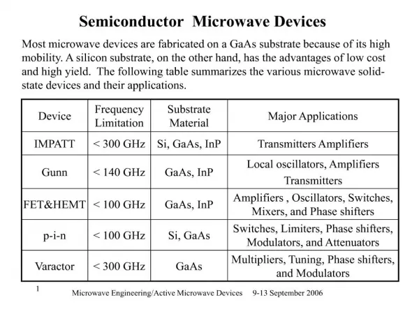
TOPICS 1.1 Introduction 1.2 Diode characteristics 1.3 Reverse Recovery characteristics 1.4 Power Diode Types- I)General Purpose ii)Fast Recovery Diode iii)Schottky Diode 1.5 Series, Parallel Operation of Diodes 1.6 GTO, Power MOSFET, IGBT- Construction, Operating principle, specification
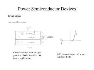
Diode characteristics • A power is a two terminal device[1,2] and p n-junction is normally formed by alloying ,diffusion ,and epitaxial growth. • When the anode potential is positive with respect cathode ,the diode is said to be forward biased and the diode conducts. A conducting diode has a relatively small forward voltage drop across it, and the magnitude of this drop depends on the manufacturing process and junction temperature .
When the cathode potential is positive with respect to the anode, the diode is said to be reverse biased. Under reverse biased condition, a small reverse current in the range of micro or mill ampere , flows and this leakage current increases slowly in magnitude with the reverse voltage until the avalanche or zener voltage Is reached.
REVERSE RECOVERY CHARACTERISTICS • The current in a forward –biased junction diode is due to the effect of majority and minority carriers . Once a diode is in a forward conduction mode and then its forward current is reduced to zero ,the diode continues to conducts due to minority carriers that remain stored in the p n – junction and the bulk semiconductor material.
The minority carriers require a certain time to recombine with opposite charges and to be neutralized. This time is called the reverse recovery tine of the diode . Fig. 1.3 shows two reverse recovery characteristics of junction diodes. • The soft - recovery type is more common. The reverse recovery time is denoted by trr and is measured from the initial zero crossing of the diode current to 25 % of maximum reverse Irr
General Purpose Diode • The general purpose rectifier diodes have relatively high reverse recovery time, typically 25 microsecond. And are used in low speed application, where recovery time is not critical. • These diodes cover current rating from less then 1 A to several thousands of amperes, with voltage rating from 50V to around 5kV. These diodes are generally manufactured by diffusion. However, alloyed types of rectifiers that are used in welding power supply are most cost effective and rugged, and their rating can go up to 1500 V, 400 A.
Fast Recovery Diodes • The fast recovery diodes have low recovery time, normally less than 5 microsecond. They are used in dc-dc and dc-ac converter circuits, where the speed of recovery is often of critical importance. These diodes cover current ratings of voltage from 50 V to around 3kv, and from less than 1 A to hundreds of amperes.
Schottky Diodes • The charge strong problem of a Pn junction can be laminated in a schottky diode. It is accomplished by setting up a barrier with a contact between a metal and a semiconductor. A layer of metal is deposited on a thin epitaxial layer of n type silicon. The potential barrier simulates the behavior of a pn junction. The rectifying action depends on the majority carriers only and as aresult there are no excess minority carrier to recombine.
Series connected diodes-with reverse bias • In many high voltage applications HVDC transmission ,one commercially diode can not meet the required voltage rating and diodes are connected in series to increase the reverse blocking capabilities Let us consider two series connected diodes is as shown in fig variable ID and VD are the current and voltage ,respectively in forward direction.
VD1 and VD2 are the sharing reverse voltages of diode D1 and D2 ,respectively in practice the V-I characteristics for the same type of diode differ due to tolerance in their production process. two v –I characteristics of such a diode in the forward bias condition both diode conduct the same amount of current and the forward voltage drop would be almost equal . • However in the reverse blocking condition, each diode has to carry the same leakage current and as a result the blocking voltage may differ significantly. IS=Is1+IR1=Is2+IR2.but IR1=VD1/R1 and IR2=VD2/R2.if the resistance are equal then R=!=R2 and two diode voltages would be significantly different. so final VD1=VD2=VS
PARALLEL CONNECTED DIODES • In high power application diode are connected in parallel to increase the current carrying capability to meet the desired current requirements .Where current sharing of diode would be in accord with their respective forward voltage drop uniform current sharing can be achieved by providing the equal inductance or by connecting current sharing resistors and this is depiciated is shown in fig . It is possible to minimize this problem by selecting
Resistor help current sharing under steady-state condition current sharing under dynamic condition can be accompanishe4d by connecting coupled inductor is shown in fig . If the current through D1 rises L1 increase and corresponding voltage of opposite polarity is include across inductor L2 . The results is a low impendence path through diode D2 and current is shifted to D2 . The inductors may generate voltage skips and they may be expensive and bulky specially at high current.
Construction of GTO • The basic structure of GTO is shown in fig. (a). As seen from the Constructionof GTO. • Fig.(a) it is basically a four layer structure similar to a conventional SCR
Fig. (b) shows the circuit symbol for the GTO.As seen from the Fig.(b) GTO is a three terminal device. Gate is control terminal. • Note the two arrows marked on the gate terminal. They indicate that the gate current for GTO can be either positive or negative. (Whereas in SCR the gate current is only positive.)
Operating Principle: • The turn on mechanism of GTO is exactly same as that of a conventional SCR. • The dependence of GTO’s breakover voltage on the magnitude of gate current is also same as that of SCR .
In short the working principle of GTO at the time of turn on and in the on state is same as that of SCR. • However the operation at the time of turn off is entirely different. • To turn off the conducting GTO ,we have to apply a negative gate current pulse at the gate terminal .
GTO Turn Off Mechanism : • The basic operation of GTO is same as that of the conventional SCR. • But the major difference between them is that the conducting GTO can be turned off by applying a negative gate current to it .Thus a positive gate current turns it on and negative gate current turns it off.
Refers to the equivalent circuit shown in Fig.(C) • Both the transistors Q1 and Q2 are in saturation when the GTO is in it’s on state . • However if the base current of Q2 could briefly be made less than the value needed for maintaining it in saturation ,then Q2 will come out of saturation and will be in the active state, this will reduce the regeneration and GTO will begin to turn off.
In order to reduce the base current of Q2,a negative gate current IG(-) must flow in the direction as shown in Fig.(c). • It can be proved that the negative gate current required for turning off a conducting GTO is given by, • IG(-) >
Where β OFF = • The parameter β OFF is known as the turn off gain. • Equation (c) clearly indicates that to turn off the GTO , the negative current I(G)(-) must be greater than the anode current divided by the turn off gain.
Advantages of GTO over SCR: • No commutation circuit required. Hence reduction in size, weight and cost. • GTOs can be used at higher switching frequencies. • Efficiency of converters using GTO is better than that using conventional SCRs .
Applications of GTO : • Inverters • Uninterruptable power supplies (UPS) • C motor drives
POWER MOSFET: • The long form of MOSFET is metal oxide semiconductor field effect transistor . • Power MOSFETs with improved current carrying capacity and off state blocking voltage capacity are now available and are replacing the power transistor in many applications.
Power MOSFETS are capable of switching at very high frequency up to about 100 KHz. • A power BJT is a current controlled device. The collector current is dependent on the base current hence the current is highly dependent on temperature. This is the serious disadvantage of power BJT. • To overcome this disadvantage .we can use a voltage controlled device such as a power MOSFET. The other advantage of MOSFET is that it require only a small input current.
PRINCIPLE OF OPERATION OF POWER MOSFET: • With gate to source voltage VGS=0 the MOSFET is equivalent to two back to back diodes connected as shown in Fig (a). The diodes are formed between n and p layers as shown. • The basic structure of MOSFET is very much similar to the BJT. The only difference is the presence of MOS capacitor that isolates the gate from the body region.
When the gate to source voltage is applied, the MOSFET turns on. The operation takes place.
FEATURES OF POWERMOSFET: • Low input current • It is a voltage control device. • Switching speed is very high. • Switching speeds are of order of nanoseconds. 5. They do not have a problem of second breakdown.
APPLICATION OF MOSFET: • In the high frequency inverters and choppers. • In the switching mode power supplies.(SMPS). • In UPS & ac motor control. 4. In stepper motor controller & brushless motor drives.
Circuit Symbols For The N Channel IGBT With Doping Densities
IGBT-insulated gate bipolar transistor BASIC STRUCTURE OF IGBT- • The vertically oriented structure of IGBT is as shown in fig. • Like al other device IGBT also uses the vertically oriented structure in order to maximize the area available for the current flow.
This will reduces the resistances offered to the current flow and hence the on state power loss taking place in the device. • This device also uses the n-type drain drift layer which also improves its breakdown voltage capacity .this is same as that in case of power MOSFETS. • This layer improves the operation of IGBT in two important aspects. B
I-V Characteristics: • 1)The I-V characteristics of IGBT is as shown in fig .in the forward direction the yare similar to those of logic level bipolar transistor he only difference here is that the controlling parameter is the gate to sources voltage and the parameter seeing0 controlled is the drain current • 2)the IGBT is the voltage controlled devices with an insulated gate.
3)the IGBT possesses all the advantage of MOSFETS due to the insulated gate it also has all the advantages of the BJT due to bipolar conduction • 4)as seen from the drain current increase with the increase in the voltage between gate and • breakdown voltage this is the voltage at which the avalanche breakdown take place .at this point the voltage across the devices and current through it both are high