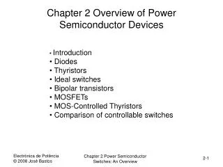
Chapter 2 Semiconductor Power Switches
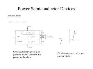
Chapter 2 Semiconductor Power Switches. “Introduction to Modern Power Electronics”, 2 nd Ed., John Wiley 2010 by Andrzej M. Trzynadlowski. Waveforms of voltage, current, and power loss in a semiconductor power switch. Fig. 2.1. Power diode: (a) semiconductor structure, (b) circuit symbol.

Chapter 2 Semiconductor Power Switches
E N D
Presentation Transcript
Chapter 2Semiconductor Power Switches “Introduction to Modern Power Electronics”, 2nd Ed., John Wiley 2010 by Andrzej M. Trzynadlowski
Waveforms of voltage, current, and power loss in a semiconductor power switch Fig. 2.1 Chapter 2
Power diode: (a) semiconductor structure, (b) circuit symbol Fig. 2.2 Chapter 2
Static voltage-current characteristic of the power diode Fig. 2.3 Chapter 2
Voltage and current waveforms during the reverse recovery period in a power diode Fig. 2.4 Chapter 2
SCR: (a) semiconductor structure, (b) circuit symbol Fig. 2.5 Chapter 2
Static voltage-current characteristic of the SCR Fig. 2.6 Chapter 2
SCR gate voltage signals: (a) single pulse, (b) multipulse Fig. 2.7 Chapter 2
Anode voltage and current waveforms during forced commutation of the SCR Fig. 2.8 Chapter 2
Triac: (a) semiconductor structure, (b) circuit symbol Fig. 2.9 Chapter 2
GTO: (a) semiconductor structure, (b) circuit symbol Fig. 2.10 Chapter 2
Circuit symbol of the IGCT Fig. 2.11 Chapter 2
BJT: (a) semiconductor structure, (b) circuit symbol Fig. 2.12 Chapter 2
Static voltage-current characteristic of the BJT Fig. 2.13 Chapter 2
Base current and collector current waveforms for turn-on and turn-off of a BJT Fig. 2.14 Chapter 2
BJT Darlington connections: (a) two-transistor, (b) three-transistor Fig. 2.15 Chapter 2
Power MOSFET: (a) semiconductor structure, (b) circuit symbol Fig. 2.16 Chapter 2
Voltage-current characteristics of power MOSFET Fig. 2.17 Chapter 2
IGBT: (a) equivalent circuit, (b) circuit symbol Fig. 2.18 Chapter 2
Voltage-current characteristics of IGBT Fig. 2.19 Chapter 2
Safe operating area for a power MOSFET Fig. 2.20 Chapter 2
Example diode and SCR modules Fig. 2.21 Chapter 2
Example power BJT (Darlington) modules Fig. 2.22 Chapter 2
Example power MOSFET modules Fig. 2.23 Chapter 2
IGBT-based modular frequency changer Fig. 2.24 Chapter 2