Download
1 / 31
330 likes | 594 Views
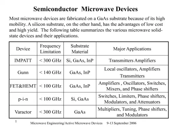
Novel SiGe Semiconductor Devices for Cryogenic Power Electronics. ICMC/CEC August-September 2005 Keystone, Colorado. Outline. Authors and Sponsors Goals and Applications Why SiGe? Designs and results SiGe heterojunction diodes Cryogenic power converter Summary. Outline.

E N D
Novel SiGe Semiconductor Devices forCryogenic Power Electronics ICMC/CEC August-September 2005Keystone, Colorado
Outline • Authors and Sponsors • Goals and Applications • Why SiGe? • Designs and results • SiGe heterojunction diodes • Cryogenic power converter • Summary
Outline • Authors and Sponsors • Goals and Applications • Why SiGe? • Designs and results • SiGe heterojunction diodes • Cryogenic power converter • Summary
Authors Rufus Ward, Bill Dawson, Lijun Zhu, Randall Kirschman GPD Optoelectronics Corp., Salem, New Hampshire Guofu Niu, Mark Nelms Auburn University, Dept. of Electrical and Computer Engineering, Auburn, Alabama Mike Hennessy, Eduard Mueller, Otward Mueller, MTECH Labs./LTE, Ballston Lake, New York GPD Optoelectronics Corporation
Sponsors US Office of Naval Research US Army Aviation and Missiles Command Defense Advanced Research Projects Agency
Outline • Authors and Sponsors • Goals and Applications • Why SiGe? • Designs and results • SiGe heterojunction diodes • Cryogenic power converter • Summary
Goals • Develop SiGe devices for cryogenic power use • Exhibit the performance advantages of SiGe versus Si for cryogenic power • Specifically: • Demonstrate prototype SiGe power diodes for cryogenic operation • Demonstrate a 100-W power conversion circuit, to deep cryogenic temperatures. • To ~ 55 K
Application Areas • For power management and distribution (PMAD) • Power conversion for storage and distribution • Power conversion for motors/generators • E.g. “All-Electric” ship • DoD applications • Cryogenic systems for ships and aerospace • Propulsion systems • Superconducting or cryogenic • Temperature ~ 60 – 65 K (for HTSC)
Outline • Authors and Sponsors • Goals and Applications • Why SiGe? • Designs and results • SiGe heterojunction diodes • Cryogenic power converter • Summary
Why SiGe? • Can incorporate desirable characteristics of both Si and Ge • Can optimize devices for cryogenic applications by selective use of Si and SiGe • SiGe provides additional flexibility through band-gap engineering (% of Ge, grading) and selective placement • All device types work at cryogenic temperatures • Diodes • Field-effect transistors • Bipolar transistors • Combinations of above (IGBTs, thyristors, ...) • Devices can operate at all cryogenic temperatures (as low as ~ 1 K if required) • Compatible with conventional Si processing
Outline • Authors and Sponsors • Goals and Applications • Why SiGe? • Designs and results • SiGe heterojunction diodes • Cryogenic power converter • Summary
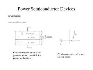
SiGe Heterostructure Diode Frontside contact SiGe epilayer P+ Si epilayer N– Si substrate N+ Backside contact (N+ backside implant)
SiGe vs Si and SiC Forward Voltage SiGe Univ. of Auburn measurements.
SiGe vs Si Reverse Recovery Univ. of Auburn measurements.
SiGe vs Si Reverse Recovery Univ. of Auburn measurements.
SiGe vs Si Reverse Recovery MTECH Labs. measurements.
SiGe vs Si Reverse Recovery MTECH Labs. measurements.
Outline • Authors and Sponsors • Goals and Applications • Why SiGe? • Designs and results • SiGe heterojunction diodes • Cryogenic power converter • Summary
48 V out 24 V in Inductor SiGe diode + Input capacitor Output capacitor + Power supply SiGe HBT Load – – Opto isolator Pulsegenerator Drive circuit ~20 – 300 K Switching pulse SiGe Boost Converter
Outline • Authors and Sponsors • Goals and Applications • Why SiGe? • Designs and results • SiGe heterojunction diodes • Cryogenic power converter • Summary
Summary • Cryogenic power conversion is of interest for a range of applications within DoD and elsewhere. • For cryogenic power conversion, SiGe devices are potentially superior to devices based on Si or Ge. • We are developing SiGe semiconductor devices for cryogenic power applications. • We have simulated SiGe diodes: results indicate improvements over Si diodes and have guided design. • We have designed, fabricated, and used SiGe diodes (and HBTs) in power converters operating at cryogenic temperatures and converting >100 W.
Outline • Authors and Sponsors • Goals and Applications • Why SiGe? • Designs and results • SiGe heterojunction diodes • Cryogenic power converter • Summary