Download
1 / 27
270 likes | 281 Views
Jitter Generation and Measurement for Test of Multi-gigabit Serial Interconnects. Sassan Tabatabaei, Freddy Ben-Zeev and Michael Lee. Purpose. RJ, DDJ, and PJ injection for receiver test Use delay line modulation Programmable DDJ Jitter measurement methodology with continuous TIA (CTIA)

E N D
Jitter Generation and Measurement for Test of Multi-gigabit Serial Interconnects Sassan Tabatabaei, Freddy Ben-Zeev and Michael Lee
Purpose • RJ, DDJ, and PJ injection for receiver test • Use delay line modulation • Programmable DDJ • Jitter measurement methodology with continuous TIA (CTIA) • Markerless measurement
Outline • Jitter injection issues • Programmable jitter injection • Continuous time interval analyzer (CTIA) • Markerless and fast RJ/DDJ measurement methodologies
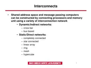
Jitter Injection Typical setup (e.g., XAUI)
Jitter Injection • Limited PJ frequency range • Large RJ may cause spurious edges • DDJ programmability very limited • Requires filter tuning • Typically not portable across applications with different bit rates
Jitter Injection Programmable setup
TraditionalTime Interval Analyzer (TIA) Operation Principles
TraditionalTime Interval Analyzer (TIA) Operation Principles
ContinuousTime Interval Analyzer (CTIA) Operation Principles
ContinuousTime Interval Analyzer (CTIA) Operation Principles
Jitter Measurement • Random jitter (RJ) • Uncorrelated to Known sources • Gaussian distribution • Data-dependent jitter (DDJ) • Inter-symbol interference • Duty-cycle distortion • Reflections Definitions
Ideal signal Real signal TIE(1) TIE(2) TIE(3) TIE(4) Jitter Measurement Definitions Time Interval Error (TIE) function:
100 TIE 50 TIE sequence (ps) 0 -50 -100 0 0.01 0.02 0.03 0.04 0.05 0.06 0.07 0.08 0.09 Time (s) 2 10 TIE FFT 0 10 Scaled FFT (ps) -2 10 -4 10 0 0.1 0.2 0.3 0.4 0.5 0.6 0.7 0.8 0.9 1.0 Normalized frequency RJ Measurement
RJ Measurement • Frequency domain deconvolution • Insensitive to PJ and DDJ • Predictable Repeatability • 3% for 8192 samples • No external marker required
Histogram for each pattern edge 120 Edge 5 Edge 4 100 Edge 2 80 Edge 3 Edge 1 Bin population 60 40 20 0 -40 0 40 80 120 TIE (ps) DDJ Measurement
DDJ Measurement • Time domain deconvolution • Per-edge time shift measurement • Insensitive to RJ and PJ (averaging) • No external marker required
DDJ Injection Example: Sinusoidal DDJ 15 CTIA (GT 4000) Scope (86100C) 10 5 Edge shift (ps) 0 -5 -10 0 20 40 60 80 100 120 Transition bit number
CTIA 10 TDS7404 8 Linear fit 6 RJ (ps) 4 3 20 22 24 26 28 30 32 0.5 RJ (ps) 0 D -0.5 20 22 24 26 28 30 32 Noise generator attenuation (db) Measurement Results (RJ) Accuracy
5.8 5.7 5.6 RJ (ps) 5.5 5.4 20 25 30 35 40 Injected DDJ (ps) Measurement Results (RJ) Immunity to DDJ 2.5Gbps, PRBS7 pattern
Measurement Results (DDJ) Accuracy 50 45 40 PRBS7 35 30 Measured peak-to-peak DDJ (ps) K28.5 25 CTIA 20 ET-DSO 15 10 0 20 40 60 80 100 120 140 160 AWG amplitude (mV)
34 35 33 34 32 Measured peak-to-peak DDJ (ps) Measured peak-to-peak DDJ (ps) 33 31 32 30 2 4 6 8 10 12 0 50 100 Injected PJ (ps) Injected RMS RJ (ps) Measurement Results (DDJ) Immunity to RJ and PJ
Conclusions • Delay line modulation with locked AWG provide flexible and programmable jitter injection method. • No need for application-specific DDJ filters • CTIA: markerless jitter separation • Virtual marker • Accurate • Fast: • No marker generation time • Compact data volume