Download
1 / 6
60 likes | 195 Views
Test Fixture to Characterize Elastomeric Interconnects. Nick Arnal, Jason Entenmann, Chris Thompson Dr. Gokhan Mucmu, Dr. Thomas Ketterl, Dr. Ken Christenson URL: www.interconnectcharacterization.weebly.com. Preliminary Design Review (PDR) November 26, 2013

E N D
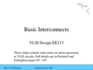
Test Fixture to Characterize Elastomeric Interconnects Nick Arnal, Jason Entenmann, Chris Thompson Dr. Gokhan Mucmu, Dr. Thomas Ketterl, Dr. Ken Christenson URL: www.interconnectcharacterization.weebly.com Preliminary Design Review (PDR) November 26, 2013 EEL 4906 Professional Issues and Engineering Design I
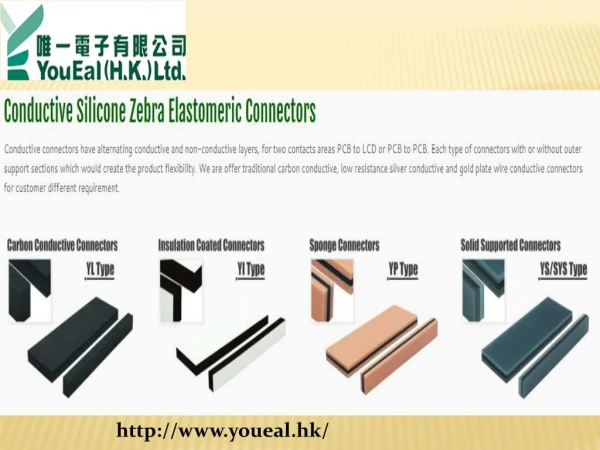
Introduction • Design a test fixture to characterize elastomeric interconnects for Harris Corporation • 2 types of elastomeric interconnects • Sample size = 5-10 of each • There exists no COTS test fixture to characterize these connectors – custom solution Test Fixture Concept Elastomeric Connector
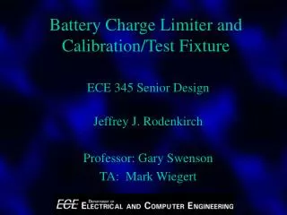
Measurements & Cycling • Fixture to withstand 500 cycles from -55°C to 125°C • S-Parameters – 0.5GHz-18GHz • Contact Resistance at DC • Continuity Temperature Cycle System Level Block Diagram
Software and Equipment Design Tools • Board design • HFSS, Pspice • Fixture design • SolidWorks • Data processing and control • Programming in C# • MATLAB for data processing • Measurement & Test Equipment • Agilent 20GHz VNA • Thermotron Temperature Chamber • 4-point Multimeter • Arduino MEGA
Action Items Final Design & CDR – January-February • Finalize RF test boards for each connector • Finalize continuity test boards • Choose and characterize low loss cables • Finalize fixture design Fabrication & Assembly – February Testing & Final Report – March-April
Website www.interconnectcharacterization.weebly.com