Download
1 / 12
130 likes | 314 Views
Electrical High-speed Serial Interconnects (e-HSSI). PH-ESE working group Kickoff meeting. Introduction. Why ?. High-speed serial links are replacing parallel buses PCBs, backplanes, cables between modules etc.

E N D
Electrical High-speed Serial Interconnects (e-HSSI) PH-ESE working group Kickoff meeting
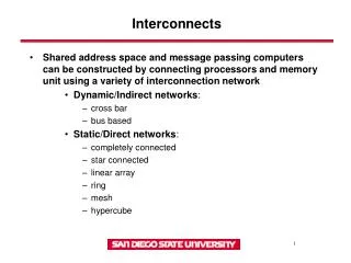
Why ? • High-speed serial links are replacing parallel buses • PCBs, backplanes, cables between modules etc. • bit rate on these links increases rapidly, approaching the fundamental limits of the transmission media • Programmable logic devices (FPGAs) support high-speed interfaces • DDR2, DDR3, QDR etc. • Boards usually contain several, high-pin-count devices • Board layout becomes very complex We need to gain experience in the domain
How? • Find experts and group them to share know-how • Identify tools and tool chains • Define methodologies and policies • Design • Simulation • Layout • Testing • Establish connections with other groups (e.g. EN-ICE-DEM), and external companies (chip and tool vendors) • Train people • Seminars, tutorials, application notes …
Design tools • Appropriate tools are required • Simulation tools (3D, 2.5D, 2D ?) • ADS, Allegro PCB SI, AWR MWO, CST MWS, HFSS, Hyperlynx, StatEye • Other ? • New tools (if any) should be compatible with existing tools • Gather experience and ensure mid-term support • At least for projects in PH-ESE
Design flow • Tool selection has strong impact on the design flow Db Policy Schematic Schematic Models Constraints Layout Db Simulation(and Layout) Simulation Layout Production Design check Testing Production Testing
Methodology • 3-D simulation of critical structures • Traces, via structures, power planes, connectors, packages etc. • Model extraction (S parameters) • Simulation of complete channels • Combination of the above structures • Simulation of complete boards • Is it feasible ?
Test and verification • Model verification • PCB materials, IC drivers etc. • How do we get them ? • Define test methods • Testing may require special tools and solutions • Design for testability • Signal probing – impact on the layout design • Built-in testing – use inherent advantage of FPGAs
Tasks • Evaluate and propose new tools • Advantages vs. disadvantages • Connection with existing CAE tools (e.g. Cadence) • Share the experience • Workinggroup meetings, SharePoint (or other) • Document: recommendations, policies etc. • EDMS
Proof of Concept • Propose a pilot project • Should be simple, but useful • Ideas ? • Demonstrate the design flow • From schematics, through simulation, to production • Use the board to validate the concept • Compare the measurement results with simulation
Next steps • TBD