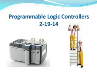
Lecture 6: Programmable Logic Controllers
Lecture 6: Programmable Logic Controllers. P rogrammable Logic Controller (PLC). PLC is a special-purpose computer optimized for industrial control tasks. Has interfacing for input and output devices such as transducers, switches, and motors.

Lecture 6: Programmable Logic Controllers
E N D
Presentation Transcript
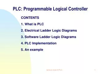
Programmable Logic Controller (PLC) • PLC is a special-purpose computer optimized for industrial control tasks. • Has interfacing for input and output devices such as transducers, switches, and motors. • Uses a programmable memory to store instructions and to implement functions such as logic, sequencing, timing, counting and arithmetic. • Easily programmed using several programming languages.
Small PLC • There are small self-contained PLC units for use with e.g. 20 digital inputs and outputs.
Modular PLC units • Also, there are modular systems which can be used for large numbers of inputs/outputs. These systems are extendible by adding input or output modules as needed.
PLC input/output types • PLC can handle digital or analog inputs/outputs, and also carry out proportional-integral-derivative control modes.
Digital Input Unit • PLC can receive DC or AC voltages of several levels.
Digital Output Unit • By the same way, PLC output can handle DC or AC voltages of several levels.
Types of PLC outputs 1- Relay type, 2- Transistor type or 3- Triac type.
Relay type output • The signal from the PLC output is used to operate a relay.
Relay type output • Relay output is able to switch currents of the order of a few amperes in an external circuit. • The relay not only allows small currents to switch much larger currents but also isolates the PLC from the external circuit. • Relays are, however, relatively slow to operate. • Relay outputs are suitable for a.c. and d.c. switching.
The transistor type output • Uses a transistor to switch current through the external circuit. • A considerably faster switching action. • Strictly for d.c.switching. • Destroyed by overcurrent and high reverse voltage. As a protection, a fuse is used.
Triac output • Strictly used to control external loads which are connected to a.c. power supply.
PLC programming languages • There are several PLC programming languages such as: • ladder diagrams (LAD), • instruction list (IL), • sequential function charts (SFC),
Ladder programming • Ladder programming is intended to be used by engineers without any great knowledge of programming. • It became adopted by most PLC manufacturers. However each tended to have developed their own versions.
Ladder diagrams • Ways of drawing the same electrical circuit
Ladder diagram • Vertical lines are called power rails. • Horizontal lines are called rungs.
Ladder diagram • Each rung on the ladder defines one operation in the control process. • Each rung must start with an input or inputs and must end with at least one output. • The term input is used for a control action, such as closing the contacts of a switch connected as an input to the PLC. • The term output is used for a device connected to the output of a PLC, e.g. a motor. • A particular device can appear in more than one rung of a ladder. For example, we might have a relay which switches on one or more devices.
Normally Open/Normally Closed Notation • Electrical devices are shown in their normal condition. • Thus a switch which is normally open (NO) until some object closes it, is shown as open on the ladder diagram. A switch that is normally closed (NC) is shown closed.
I/O addresses • The inputs and outputs are identified by their addresses. • This is the address of the input or output in the memory of the PLC. • Each PLC manufacturer has its own notations for addressing input and outputs. • Here, we will use the addressing notations used by Siemens.
Discrete I/O Numbering I0.0 Q2.0 • Idesignates a discrete input and • Qdesignates a discrete output. • The first number identifies the byte. The second number identifies the bit. • Image register space for digital I/O is always reserved in increments of eight bits (one byte).
Analog I/O Numbering AIW 0 AQW 2 • Each analog I/O point is associated with a 16-bit word in the S7-200 PLC and is identified by AI (for analog input) or AQ (for analog output) followed by a W (representing a word of memory) and a starting byte number. • Analog I/O words start on even-numbered bytes (such as 0, 2, or 4). • The following example shows the addressing for one sample application.
Example • For the following ladder rung, output A occurs when input A occurs. Output B only occurs when both input A and input B occur.
Latching • There are often situations where it is necessary to hold an output energized, even when the input ceases. • A simple example of such a situation is a motor which is started by pressing a push button switch. • Though the switch contacts do not remain closed, the motor is required to continue running until a stop push button switch is pressed. • The term latch circuit is used for the circuit used to carry out such an operation. It is a self-maintaining circuit in that, after being energized, it maintains that state until another input is received.
Start stop circuit • The following circuit is used to start and stop a motor using push buttons. • In the normal state, push button Ais open and push button Bclosed. • When Ais pressed, the motor starts. • When Ais released, the holding contacts maintain the circuit and hence the power to the motor. • To stop the motor, Bis pressed. This disconnects the power to the motor and the holding contacts open. Thus when B is released, there is still no power to the motor. • Thus we have a motor which is started by Aand stopped by B.
Safe and Unsafe Stop switches • The stop switches has to be very carefully considered in order to ensure a safe system. • The previous start-stop circuit is unsafe. • The nature of electric circuits is that "open" failures (open switch contacts, broken wire connections, open relay coils, blown fuses, etc.) are statistically more likely to occur than any other type of failure.
Safe and Unsafe Stop switches • Imagine that the stop switch fails. It most likely fails open (becomes open permanently). In this case, the system cannot be stopped. • A stop switch is not safe if it is normally open and has to be closed to give the stop action.
A better arrangement is to program the stop switch in the ladder program as open and use a stop switch that is normally closed and operating opens it.