Programmable Logic Controllers 2-19-14
Programmable Logic Controllers 2-19-14. PLC Components and Modules. Input ports/modules Output ports/modules Chassis with power supply Opto isolators – internal and external Relays - Electro-mechanical, Solid state CPU with flash memory Network processors

Programmable Logic Controllers 2-19-14
E N D
Presentation Transcript
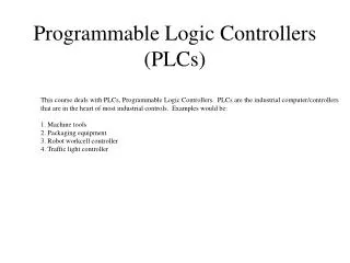
PLC Components and Modules • Input ports/modules • Output ports/modules • Chassis with power supply • Opto isolators – internal and external • Relays - Electro-mechanical, Solid state • CPU with flash memory • Network processors • Programming language modules • External devices – Relay banks, Pneumatic solenoid valves, Mechanical solenoid actuators
PLC H/W & S/W Hard Ware • Compact or Modular build – Chassis, Power supply, CPU, and I/O modules. • PLCs are becoming smaller and more economical. • PLC functions remain the same – General purpose control device for an automated system. Programming • Mostly based on Relay Ladder Logic, programmed in a ladder like diagram or in mnemonics. • Some based on state logic or block flow diagram. • Scan Cycle – Output activation on each rung meeting input conditions, followed by I/O refresh between cycles.
Ladder Logic Diagram • Consists of “rungs” that specify the input conditions (“switches”) needed to energize the output relays (“coils”). • Outputs may be routed back as inputs. The input switch setting may not be altered internally. • Input values are updated at the beginning of a scan cycle. The outputs at the end. Immediate updates possible. • Rungs are scanned from top to bottom, from left to right. Conditional branching results in split scanning flow. • Input and output signals may be digital, analog, and pulses. Analog signals are converted into digits – ADC & DAC. • The scan cycle time is typically less than ten milliseconds, depending on the program size and the processor speed.
Boolean Logic Operation: AND (∩, •), OR (U, +), NOT ( , ~ , /) AND: Intersection; OR: Union; NOT: Negation ISO Symbols: AND, OR, AND, OR IC Gate Logic: AND, OR, NAND, NOR, XOR XOR – (X1 U X2) ∩ (X1 ∩ X2) (X1 ∩ X2) U(X1 ∩ X2) DeMorgan’s Equivalence: X1 + X2 X1 ·X2 X1 · X2 X1+ X2
Inputs and Outputs Inputs Momentary switches (N.O., N.C., Rising Edge, Falling Edge) Pulse inputs from pulse counters (e.g., encoders). ADC inputs from analog sensors. Outputs Normal (Relay), SET (Latch), RESET (Unlatch) Pulse outputs for stepping devices (e.g., stepper motors) DAC outputs to analog actuators. Timers and Counters Input – Timer advances while the input is TRUE. A non-cumulative timer resets to zero if the input becomes FALSE. Output – Timer ON, Current time, Set value reached Counters work similarly, but do not require steady input.
PLC Network Ethernet For communication with PC or supervisory computer. Linkage to other parallel or daisy chained PLCs. DeviceNet For lateral device level communication. 4-wire serial connection – 2 for signals, 2 for power supply. Developed by Allen-Bradley. Control Net For remote PLC system control. RG-6 coaxial cable with BNC connector.
Mnemonics for Ladder Logic STR, STRN to start a main or sub rung AND, ANDN, -PD, -ND to add serial components OR, ORN, -PD, -ND to add parallel components ANDB, ORB to append a sub-rung to the main rung OUT, SET/RST (LATCH/UNLATCH) Outputs TMR, CTR Timers, Counters
Internal Variables & Pit Falls Internal Variables Not wired to the input or the output ports. Not bound by I/O ports. A set/reset type. May be used as an input as well as an output. Uses of Internal Variables To drive timers requiring an uninterrupted true state of the input. To avoid unintended, collateral activation of outputs. Pit Falls in PLC programming In each scan cycle, the outputs of all rungs are processed as long as the input conditions are true at the start of the cycle. Use of temporary output variables as part of the input condition keeps unintended outputs from activating. Branching in program flow does not keep the PLC from scanning the rungs following the branch off. This is a fundamental difference between the traditional programming flow and the PLC ladder logic.
PLA/IC Gate Logic & LLP Tips Direct Correspondence with IC Gate Logic programming Excluding timers and counters, the rung conditions can be programmed into a Programmable Logic Array chip, or although cumbersome, into standard gate logic ICs. This includes Rising Edge and Falling Edge conditions. Tips in PLC Programming Make a liberal use of temporary variables. Do not reuse timers and counters. Use X’s (sensors) and Y’s (actuators) sequentially with a reference table for what they represent. Keep the rungs short and straightforward. Avoid branching, loops, and subroutine like structures.