Programmable Logic Devices and Architectures: A Nano-Course
1.07k likes | 1.39k Views
Programmable Logic Devices and Architectures: A Nano-Course. R. Katz Grunt Engineer NASA. What We Will Cover. Various programmable logic types Device architectures Device performance Packaging Reliability Some radiation considerations Lessons learned. What You Will Not Learn.

Programmable Logic Devices and Architectures: A Nano-Course
E N D
Presentation Transcript
Programmable Logic Devices and Architectures:A Nano-Course R. Katz Grunt Engineer NASA
What We Will Cover • Various programmable logic types • Device architectures • Device performance • Packaging • Reliability • Some radiation considerations • Lessons learned
What You Will Not Learn You will not learn much. This course is only a brief introduction to key concepts and issues, not a comprehensive and in-depth tutorial. Because of time limitations, sections have been either scaled back or eliminated.
References References are available for most slides • Original work • available on http://rk.gsfc.nasa.gov • Manufacturers’ data sheets, application notes • Papers and reports • Many from MAPLD 1998, 1999, 2000 • Standard logic design textbooks
Lessons Learned (1) Barto's Law: Every circuit is considered guilty until proven innocent.
Lessons Learned (2) Launched: March 4, 1999 Failed: March 4, 1999
Applications Some Application Types • Existing SSI/MSI Integration • Obsolete/"Non-Space-Qualified" Component Replacement • Bus Controllers/Interfaces • Memory Controller/Scrubber • High-Performance DSP • Processors • Systems on Chip • Many Other Digital Circuits
ESA Core SSTL Core Complex System-on-Chip CAN Network >100Mbps RX0 CLK RX1 CLK RX2 CLK TX CLK CAN BUS LVDS POR HDLC RX Controller HDLC RX Controller HDLC RX Controller HDLC TX Controller Parallel Port Interface CAN Interface FIFO FIFO FIFO FIFO FIFO AMBA AHB AMBA AHB AMBA AHB AMBA AHB AMBA AHB AMBA AHB AMBA AHB AMBA AHB System Bus AMBA AHB LEON Sparc V8 CORDIC Coprocessor ROM LUT Bootstrap EDAC DECDED CF+ I/F True IDE PIO UART +2.5V +3.3V Linear Regulator 1M*64 SRAM 170Mbyte Microdrive SP TC Debug +3.3V
Programmable Elements Overview • Antifuse • ONO and Metal-to-Metal (M2M) • Construction • Resistance • SRAM • Structure • Quantity • EEPROM/Flash • Ferroelectric Memory • Summary of Properties
Antifuse Technology Polysilicon ONO Metal - 3 Top Electrode Amorphous Silicon FOX N++ Dielectric (optional) thermal oxide Metal - 2 Bottom Electrode CVD nitride thermal oxide Metal-to-Metal Antifuse (Actel, UTMC, Quicklogic) ‘Pancake’ Stack Between Metal Layers Used in 3.3V Operation in Sea Of Gates FPGA Other devices (as shown later) Program at ~ 10V Typical thickness ~ 500 - 1000 Å R = 20 - 100 ohms ONO Antifuse (Actel) Poly/ONO/N++ Heavy As doped Poly/N++ Thickness controlled by CVD nitride Programs ~ 18V Typical Toxono ~ 85 Å Hardened Toxono ~ 95 Å R = 200 - 500 ohms
Antifuse Cross-Sections Amorphous Silicon (Vialink) ONO (Act 1)
M2M Antifuse inMulti-layer Metal Process Vialink SX, SX-A, and SX-S M2M = Metal-to-metal
Programmed Antifuse Resistance Distributions The resistance of programmed antifuses is stable with temperature, varying less than 15 percent per 100°C.
SRAM Switch Technology Configuration Memory Cell Read or Write Data Routing Connections
Summary of Current Technology Type Re-programmable Volatile Technology Radiation Hardness Fuse No No Bipolar Hard EPROM Yes No UVCMOS Moderate EEPROM YES, ICP No EECMOS Moderate SRAM YES, ICP Yes CMOS Soft Antifuse No No CMOS+ Hard FRAM Yes, ICP No Perovskite Hard1 Ferroelectric Crystal 1Get Bennedetto paper to verify.
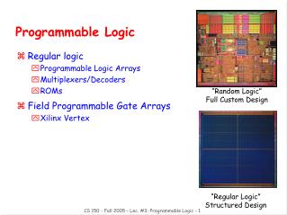
FPGA Architecture • Assembly of Fundamental Blocks • Hierarchical • Integration of Different Building Blocks • Logic (Combinational and Sequential) • Dedicated Arithmetic Logic • Clocks • Input/Ouput • Delay Locked Loop • RAM • Routing (Interconnections) • Channeled Architecture • Sea-of-Module Architecture
Channeled Routing Structure Modules Unprogrammed Antifuse Programmed Antifuse Horizontal Track Modules Vertical Track Horizontal Control
Sea-of-Modules Structure • Some programmable elements require silicon resources • SRAM flip-flops • ONO antifuse • Metal-to-metal antifuses are built above the logic • No routing channels • Higher density • Faster
UT4090 Architecture RAM Blocks Logic Array RAM Blocks
Virtex Architecture Overview IOB = I/O Block DLL = Delay-locked loop BRAM = Block RAM (4,096 bits ea.) CLB = Configurable Logic Block
Logic Modules • Actel (Act 1,2,3, SX) • Basics • Flip-flop Construction • UTMC/Quicklogic (i.e., UT4090) • RAM blocks • Xilinx (i.e., CQR40xxXL, Virtex) • LUTs/RAM • Carry Logic/Chain • Mission Research Corp. (MRC) - Orion • Atmel - AT6010
Act 2 Logic Module: C-Mod 8-Input Combinational function 766 possible combinational macros1 1”Antifuse Field Programmable Gate Arrays,” J. Greene, E. Hamdy, and S. Beal, Proceedings of the IEEE, Vol. 91, No. 7, July 1993, pp. 1042-1056
Act 2 Flip-flop Implementation Feedback goes through antifuses (R) and routing segments (C) Hard-wired Flip-flop Routed or “C-C Flip-flop”
UT4090 Logic Module • Antifuse Configuration Memory • Mux-based • Multiple Outputs • Wide logic functions
UT4090 RAM Module • Dual-port • 1152 bits per cell • Four configurations • 64 X 18 • 128 X 9 • 256 X 4 • 512 X 2
XC4000 Series CLBSimplified CLB - Carry Logic Not Shown RAM LUTs for Logic or small SRAM Two Flip-flops
XQR4000XL Carry Path Placement is important for performance. General interconnect
Carry Logic Operation Effective Carry Logic for a Typical Addition - XQR4000XL
Memory Architecture • Radiation-hardened PROM • Configuration memory • EEPROM
Rad-Hard PROM Architecture No latches in this architecture
E2 Memory Array Edge Detect & Latches Row AddressDecoder Column AddressDecoder Row AddressLatches Column AddressLatches 64 Byte Page Buffer Control Latch Control Logic Timer I/O Buffer/ Data Polling W28C64 EEPROMSimplified Block Diagram A6-12 A0-5 CE* WE* Latch Enable OE* CLK VW I/O0-7 PE RSTB
Input/Output ModulesA Brief Overview • Basic Input/Output (I/O) Module • Some Features • Slew Rate Control • Different I/O Standards • Input Delays • Banks • Deterministic Powerup • Cold Sparing
Act 1 • Many families have slew rate control to limit signal reflections and ground bounce. • Different families drive their outputs to different levels.
Different I/O Standards Virtex 2.5V Example I/O Standard Input Ref Output Board 5V Voltage Source Termination Tolerant (VREF) Voltage Voltage (VCCO) (VTT) LVTTL 2–24 mA N/A 3.3 N/A Yes LVCMOS2 N/A 2.5 N/A Yes PCI, 5 V N/A 3.3 N/A Yes PCI, 3.3 V N/A 3.3 N/A No GTL 0.8 N/A 1.2 No GTL+ 1.0 N/A 1.5 No HSTL Class I 0.75 1.5 0.75 No HSTL Class III 0.9 1.5 1.5 No HSTL Class IV 0.9 1.5 1.5 No SSTL3 Class I &II 1.5 3.3 1.5 No SSTL2 Class I & II 1.25 2.5 1.25 No CTT 1.5 3.3 1.5 No AGP 1.32 3.3 N/A No
Deterministic Power-upSX-S Example VCCA VCCI • Pull-ups /downs are selectable on an individual I/O basis • Pull-up follows VCCI • Pull-downs and pull-ups are dis- abled 50 ns after VCCA reaches 2.5V and therefore do not draw current during regular operation. • Once VCCA is powered-up, 50ns is required for a valid signal to propagate to the outputs before the pull-ups /downs are disabled RTSX-S Pull-up enabled PRE Input Driven low or external POR Signal CLR Pull-down enabled
Powered-up Board 3.3/5 Volts Powered-down Board VCCI RTSX-S 0 Volts GND Active Bus or Backplane VCCI RTSX-S GND I/O w/ ” Hot-Swap” Enabled does not sink current Cold Sparing - SX-S
Packaging and Mechanical Aspects • Package Types • Dual In-line Package (DIPs) • Flatpacks • Pin Grid Arrays (PGAs) • Ceramic Quad Flat Packs (CQFP) • Plastic Quad Flat Pack (PQFP) • Plastic Package Qualification • Lead/Ball Pitch • Mass Characteristics • Shielding
Shielded Packages - Rad-Pak™ • This package, with tie bar, 24 grams • Shielding thickness may vary between lots • Shield is 10-90/copper-tungsten • Density of shield is ~ 18 g/cm3 (need to verify) • EEPROMs and other devices also packaged similarly