Download
1 / 51
530 likes | 555 Views
Explore the definition and functions of registers and counters in digital design. Learn about shift registers, ripple counters, and synchronous binary counters. Discover their importance in computer systems and memory processes.

E N D
ENG2410Digital Design: Week #8“Registers & Counters” S. Areibi School of Engineering University of Guelph
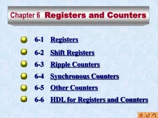
Week #8 Topics • Definition of Register and Counter • Registers, Shift Registers • Ripple Counters • Synchronous Binary Counters • BCD Counters
Resources Chapter #7, Mano Sections • 7.1 Registers and Load Enable • 7.6 Shift Registers • 7.6 Ripple Counters • 7.6 Synchronous Binary Counters
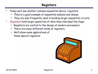
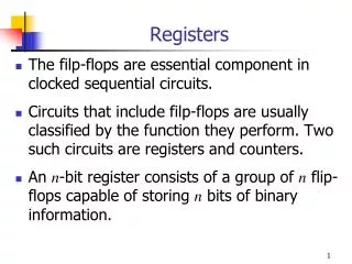
Registers: Definition Register – a set of flip-flops • May include extensive logic to control state transition • Registers also refered to as fast memory for storing data in a computer
Counters: Definition Counter • Register that goes through sequence of states as it is clocked • We designed a simple counter in the previous Lecture using T Flip Flops! 000 001 010 011 111 110 101 100
Simple Register (No External Gates) Inputs • Functionality • Store D (D0,D1,D2,D3) • On pos-edge of Clock • Clear signal normally high • Power-up reset Outputs
Structure A memory for storing program and data. The memory consists of the word with the same length Central Processing Unit (CPU): A control unit (control path) featuring a program counter for controlling program execution An arithmeticand logic unit (ALU) also called data path for program execution Computer Systems Memory Processor or Central processing unit Datapath Data and Instructions Data Registers Control Path Address register Instruction register PC Address
Clocking • The transfer of new info into a register is referred to as loading the register. • Typically we don’t want to load every clock • We gate the clock!! (Disable the clock)!! • We try to avoid gating!! (Timing issues) Disable the Clock
Alternative • If load ‘H’, then D goes through • Otherwise, Q is fed back • Keep same value • No clock gating • Why add all this logic? • Because D FF doesn’t have “no change” behavior
Shift Registers • A shift register is a chain of flip-flops in cascade, with the output of one flip-flop connected to the input of the next flip-flop. • It is a register capable of shifting its stored bits laterally in one or both directions. • All flip-flops receive a common clock pulse, which activates the shift from each stage to the next. 1 0 1 1 1 0 1 1
Simple 4-bit Shift Register • Every bit shifts to the right at every clock edge. • New information will enter via Si and leave from So
Simple 4-Bit Shift Register: Diagram • Clocked in common • Just serial in and serial out Q3 Q0 Q1 Q2 SO
VHDL for Shift Registers -- 4 bit Shift Register with Reset library ieee; use ieee.std_logic_1164.all; entity srg_4_r is port (CLK, RESET, SI : in std_logic; Q : out std_logic_vector(3 downto 0); SO : out std_logic); end srg_4_r; architecture behavioral of srg_4_r is Signal shift : std_logic_vector (3 downto 0); begin process (CLK, RESET) begin if (RESET = `1’) then shift <= `0000’; elsif (CLK’eventand CLK = `1’)) then shift<= shift(2 downto 0) & SI; end if; end process; Q <= shift; S0 <= shift(3); end behavioral ; Reset
Bidirectional Shift Register • Shift either way (Left or Right) • Now we have following possible inputs • Parallel load • Shift from left • Shift from right • Also “no change”
Schematic One stage of a bidirectional shift register with parallel load
Shift Register with Parallel Load • Load any value to the shift register • The shift register can then shift information one bit at a time
Shift Register with Parallel Load Schematic
Shift Registers (Summary) • Capability to shift bits • In one or both directions • Usage? • Part of standard CPU instruction set • Cheap Multiplication/Division • Serial communications
Counters • Counter is a register – but has states • Also goes through sequence of states – counts – on clock or other pulses • Examples: • Binary Counter • Counts through binary sequence • n bit counter counts from 0 to 2n – 1 • BCD Counter • Any Sequence Counter
Synthesis Using T Flip Flops • Design a counter that counts from “000” to “111” and then back to “000” again. • Use T Flip-Flops Where do we start? Start with a state diagram.
A Counter using T Flip Flops“Synchronous Counters” 000 001 010 011 111 110 101 100 • Create the State Table (use Excitation Table) • Minimize the Boolean function • Draw a circuit diagram
Example: T Flip Flop Synthesis 0 TA0 = 1 TA1 = ?? TA2 = ??
A2 A1 1 T T T A0 T Flip Flops “Synchronous” By using K-maps we can minimize the flip flop input equations.
Asynchronous Counters • Asynchronous counters are yet another type of counters where not all flip flops are driven by the global clock. • Ripple counters are asynchronous counters that are easy to design.
Binary Counter with Parallel Load • Counters employed in digital systems quite often require a parallel-load capability for transferring an initial binary number into the counter prior to the counter operation. • When “load” is equal to 1, the input load control disables the count operation and causes a transfer of data from the four parallel inputs to the four outputs. • The carry output C0 becomes a 1 if all flip-flops are equal to 1 while the count input is enabled. • This feature is useful for expanding the counter to more stages
BCD Counters BCD Counters can also be designed using individual flip-flops and gates
BCD Counter using Binary Counters • The “Binary Counter” with parallel load can be converted into a synchronous BCD counter (How?) • By connecting an external AND gate to the load control (as shown in the Figure).
Arbitrary Count Sequence • One more type of counter is useful • Count an arbitrary sequence • Maybe you need a sequence of states
Circuit and State Diagram 011 111
VHDL for Counters CLK Q3 Q2 -- 4 bit Binary Counter with Reset library ieee; use ieee.std_logic_1164.all; entity count_4_r is port (CLK, RESET, EN : in std_logic; Q : out std_logic_vector(3 downto 0); CO : out std_logic); end count_4_r; architecture behavioral of count_4_r is Signal count : std_logic_vector (3 downto 0); begin process (CLK, RESET) begin if (RESET = `1’) then count <= `0000’; elsif (CLK’event and CLK = `1’) and (EN = `1’)) then count <= count + “0001”; end if; end process; q <= count; C0 <= `1’ when count = “1111” and EN = `1’ else ‘0’; end behavioral ; Q1 RESET Q0 EN CO
Then shift through adder into A. Added to 0 if A is empty. Adds one bit at a time Stores carry one clock Serial Addition Initially reset all registers Register A accumulates At same time, new value going into B Shift value in serially
Hardware Comparison Serial vs. parallel adder • One full adder vs. n adders • Serial takes n clock cycles, parallel only one clock cycle
Serial Transfer (8-bit Shift Register) Could shift data in What’s on wire at each clock? Clocked 4 times