Download

1 / 41
420 likes | 586 Views
Explore disk drive structure, access time components, and scheduling algorithms to optimize system performance. Learn about seek time, rotational latency, and disk scheduling techniques such as FCFS, SSTF, SCAN, C-SCAN, and C-LOOK.

E N D
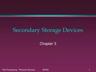
Cylinder Disk Architecture Sector Disk head Track 3500-7000 rpm
Disk Structure • Disk drives are addressed as large 1-D arrays of logical blocks, where the logical block is the smallest unit of transfer • The 1-D array of logical blocks is mapped onto the sectors of the disk sequentially • Sector 0 is the 1st sector of the 1st track on the outermost cylinder • Mapping proceeds in order through that track, then the rest of the tracks in that cylinder, and then through the rest of the cylinders from outermost to innermost
Disk Structure Logical view: 1-D array logical block Cylinder 2 Sector 0 Cylinder 1 Sector 1 Cylinder 0 Disk Physical view
Disk Scheduling • The OS is responsible for using hardware efficiently -- for the disk drives, this means having a fast accesstime and high disk I/O bandwidth • Access time has two major components • 1. Seek time: move the head to the destination cylinder • 2. Rotational Latency: time for disk to rotate the desired sector to the disk head
Cylinder Disk Architecture Seek time “seek to the cylinder” = 10 -2 second Latency time: “Rotate to sector” = 0.5 x (60/6000) ~ 5x10 -3 second Sector Disk head Track Transmission Time: Transfer bytes into memory ~ 10 -4 sec (1KB block size/(10MB/s) DMA rate) 3500-7000 rpm
Disk Scheduling • Minimize seek time; seek time seek distance • Disk bandwidth= total # of bytes/(time: 1st request to last request) • Some algorithms • 1. First-Come-First-Served (FCFS) • 2. Shortest-Seek-Time-First (SSTF) • 3. SCAN (Elevator algorithm) • 4. Circular-SCAN (C-SCAN) • 5. C-LOOK (LOOK)
1. First-Come-First-Served (FCFS) Queue= 98, 183, 37, 122, 14, 124, 65, 67 Head starts at 53 0 14 37 53 65 67 98 122 124 183 199 45 85 146 85 108 110 59 2 640 tracks
1. First-Come-First-Served (FCFS) • Easy to program and intrinsically fair. • Ignore position relationships among pending requests. • Acceptable when the loading on a disk is light and requests are uniformly distributed. Not good for medium and heavy loading.
2. Shortest-Seek-Time-First (SSTF) • Select the request with minimum seek time from the current head position. • A form of SJF scheduling • Better than FCFS in general. • It may cause starvation of some requests.
12 2 30 23 84 24 2 59 236 tracks 2. Shortest-Seek-Time-First (SSTF) Queue= 98, 183, 37, 122, 14, 124, 65, 67 Head starts at 53 0 14 37 53 65 67 98 122 124 183 199
SSTF • It is not optimal • Consider the servicing sequence (from the left): 53, 37, 14, 65, 57, 98, 122, 124, 184. • The total head movement is 208 tracks. • This is 28 tracks less than that of SSTF.
12 2 30 23 84 24 2 59 16 23 51 2 31 24 2 59 236 tracks (SSTF) 208 tracks SSTF not optimal Queue= 98, 183, 37, 122, 14, 124, 65, 67 Head starts at 53 0 14 37 53 65 67 98 122 124 183 199
3. SCAN (Elevator algorithm) • The disk arm starts at one end of the disk, and moves toward the other end, servicing requests until it gets to the other end of the disk, where the head movement is reversed and servicing continues. • Most disk scheduling strategies actually implemented based on SCAN • Improve throughput and mean response time.
3. SCAN (Elevator algorithm) Queue= 98, 183, 37, 122, 14, 124, 65, 67 Head starts at 53 16 23 14 65 2 31 24 2 59 014 37 53 65 67 98 122 124 183199 236 tracks
3. SCAN (Elevator algorithm) • Eliminate much of discrimination in SSTF • much lower variance in response time. • The requests at the other end of the disk wait the longest time. • But the upper bound on head movement for servicing a disk request is just twice the number of disk tracks.
4. C-SCAN • A variant of SCAN which provides a more uniform wait time than SCAN. • The head moves from one end of the disk to the other end, servicing requests as it goes. When it reaches the other end it immediately returns to the beginning of the disk, without servicing any requests on the return trip . • It has very small variance in response time; that is it maintains a more uniform wait time distribution among the requests.
4. Circular-SCAN (C-SCAN) Queue= 98, 183, 37, 122, 14, 124, 65, 67 Head starts at 53 12 2 31 24 2 59 16 199 14 23 0 14 37 53 65 67 98 122 124 183 199 382 tracks
5. C-LOOK • C-LOOK are the practical variants of C-SCAN. • The head is only moved as far as the last request in each direction. • When there are no requests in the current direction the head movement is reversed. • C-SCAN always move the head from one end of the disk to the other.
5. C-LOOK (Modified C-SCAN) Queue= 98, 183, 37, 122, 14, 124, 65, 67 Head starts at 53 12 2 31 24 2 59 16 199 14 23 0 14 37 53 65 67 98 122 124 183 199 169 322 tracks
Selecting a Disk-Scheduling Algorithm • It is possible to develop an optimal algorithm but the computation needed may not justify the savings over SSTF or SCAN scheduling algorithms. • The SCAN and C-SCAN (or LOOK and C-LOOK) algorithms are more appropriate for systems that place a heavy load on the disk.
Selecting a Disk-Scheduling Algorithm • If the queue seldom has more than one outstanding request then all disk scheduling algorithms are degraded to FCFS and thus are effectively equivalent. • Some disk controller manufacturers have moved disk scheduling algorithms into the hardware itself. • The OS sends requests to the controller in FCFS order and the controller queues them and execute them in some more optimal order.
Disk Management • Low-level formatting, or physical formatting -- Dividing a disk into sectors that the disk controller can read and write. • To use a disk to hold files, the OS still needs to record its own data structures on the disk. • Partition the disk into one or more groups of cylinders • Logical formatting for “making a file system”.
Swap-Space Management • Swap-space -- Virtual memory uses disk space as an extension of main memory. • Goal: to provide best throughput for virtual-memory system.
Swap-Space File system Swap space User program Main Memory Disk
Swap-Space Use • Systems that implement swapping may use swap space to hold the entire process image, including the code and data segments. (Paging systems may simply store pages that have been pushed out of main memory.) • Size of swap space: few MB to hundreds of MB • UNIX: multiple swap spaces, usually put on separate disks. Unix copy entire processes between contiguous disk regions and memory.
Swap-Space Location • 1. normal file system: • simply a large file within the file system • easy to implement, but inefficient due to the cost of traversing the file-system data structure • 2. separated disk partition(more common): • No file system or directory structure is placed on this space. • A separate swap-space storage manager is used to allocate and de-allocate the block (optimized for speed not storage utilization)
Swap-Space Management • BSD 4.3 • Preallocation: allocates swap space when process starts; holds text segment (the program) and data segment • kernel uses swap maps to track swap-space use • file system is consulted only once for each text segment; • pages from data segment are read in from the file system, or created, and are written to swap space and paged back in as needed.
Swap-Space Management • Solaris 2 • allocates swap space only when a page is forced out of physical memory, not when the virtual memory page is first created (modern computer has larger main memory)
Disk Reliability Disk failure causes a loss of data and significant downtime while disk is replaced and data restored.
Disk striping (interleaving) • A group of disks is treated as one storage unit. • Each data block is divided into several sub-blocks. • Each sub-block is stored on a separate disk. • This reduces disk block access time and can fully utilize disk I/O bandwidth. • Performance improvement: All disks transfer their subblocks in parallel
RAID • RAID: Redundant Arrays of Inexpensive Disks • It improves performance (especially price performance ratio) and reliability (with duplication of data).
RAID Level 1 • known as Mirroring or shadowing, • makes a duplicate of all data files onto a second disk. • 50% disk space utilization • the simplest RAID organization.
RAID 1 : Mirroring (Shadowing): WRITE c : FtDisk
RAID 3 : Block Interleaved Parity • An extra block of parity data is written to a separate disk. • Example • if there are 9 disks in the array then sector 0 of disks 1 to 8 have their parity computed and stored on disk 9. The operation takes place on bit level for each byte.
Block Interleaved Parity: Input 1 Input 2 Output 1 1 0 1 0 1 0 1 1 0 0 0 Truth Table of XOR 0 1 1 1 1 0 1 0 1 Parity Disk Disk 2 Disk 1
1 Block Interleaved Parity Input 1 Input 2 Output 1 1 0 1 0 1 0 1 1 0 0 0 Truth Table of XOR 0 ? 1 1 1 0 1 0 1 Disk 3 Disk 2 Disk 1
Block Interleaved Parity • If one disk crashes we can re-compute the original data from the other data bits plus the parity. • It has been shown that with a RAID of 100 inexpensive disks and 10 parity disks the mean time to data loss (MTDL) is 90 years. • MTDL of a standard large expensive disk is 2 or 3 years.
RAID 3 • Utilization issue: • stripping data across a minimum of two drives while using a third drive to store each byte’s parity bit. 2/3 disk utilization (3 disks) • Performance issue: • During writing, because updating any single data subblock forces the corresponding parity subblock to be recomputed ad rewritten. • Can manage only one data transfer at a time per array (for example, a single read or write)
RAID Level 5 • Similar to RAID 3; all devices are used for data storage, with parity bit recording distributed across all drives. • RAID 5 provides the best combination of over-all data availability and fault-tolerant protection.
RAID Info • Read the article about RAID in the course webpage: SunEXpert, March 1996, Vol. 7, No. 3, “RAID: Wasted Days, Wasted nights”