Download
1 / 31
360 likes | 588 Views
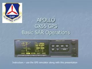
Introduction to the GX55 GPS Receiver for VFR and SAR Navigation. Instructor Bob McCabe, Capt., CAP AGI, IGI, CFI. Course Objectives. Describe the basic operations of the Apollo GX55 GPS Receiver and its use in VFR and SAR navigation

E N D
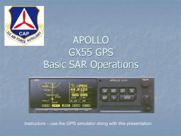
Introduction to the GX55 GPS Receiver for VFR and SAR Navigation InstructorBob McCabe, Capt., CAPAGI, IGI, CFI
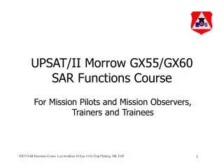
Course Objectives • Describe the basic operations of the Apollo GX55 GPS Receiver and its use in VFR and SAR navigation • Explain operating modes of greatest practical value to CAP VFR and SAR pilots. • Provide course materials that serve as a handy reference for proficiency and mission flight training and operations.
Expected Results • At the conclusion of this course the student should have a basic understanding of GX55 GPS Receiver terminology and operating principles and should be able to self-train to attain proficiency in using the GX55 for actual VFR and SAR navigation. • The student is encourages to read the Apollo GX Series Users Guide, Rev 2, to gain an in-depth understanding of all operating modes and features (available at www.upsat.com/gx_docs.shtml)
Course Outline • Navigation Terms • Key Features of the GX55 • Front Panel Description • Controls • Hard Keys • Smart Keys • External Indicators/Annunciators • Operating Summary • Frequently Used Display Pages • Practical Exercises
Key Features • 30 Reversible Flight Plans with 20 legs • Automatic Waypoint Sequencing • 500 User-Definable Waypoints • Automatic Display Intensity Control • Automatic/Manual Mag Variation • Direct-To Nav Function • SAR Nav modes: parallel track, parallel line, creeping line, expanding square. • Nearest Waypoint Search • Internal database of Airports, VORs, NDBs, Intersections, Frequencies, Airport Info and Special Use Airspaces.
Controls Smart Key Annunciators Power - Turn for on/off Hard Keys Smart Keys (context sensitive) • Small (Inner) Knob/ Large (Outer) Knob - • Select pages, edit characters & values, or other options • LARGE knob moves cursor; SMALL knob changes characters • Either may change pages depending on function
Hard Keys • NAV (Navigation) - Press key to reach navigation functions. Press twice to go to “top” page. • NRST (Nearest Waypoint) - Displays the 20 closest waypoints to your position by distance. Waypoint type is selectable. • INFO (Information) - Accesses supplementary information about a waypoint. Press INFO a second time to return to the previous display. • SEL (Select) - Activates editing or selection of options. Editing is active on the items that flash on the display. Press SEL a second time to deactivate selection.
Hard Keys • MAP (Geographic Moving Map) - Starts the moving map function. Press twice to go to “top” page (MAP plus NAV mode). • DIRECT-TO - Used to define a direct course from your present position to a waypoint. Press twice to enter an OBS desired track. • ENTER - Enters and saves the information flashing on the display. If the ENTER key is not pressed after editing, any changes made are not saved.
Smart KeysMAP plus NAV, and MAP Only Mode • Press to access second set of smart keys: NDB, USER, SCAN • Press again to return to first set of smart keys. Current Leg Waypoint Waypoint Display Annunciators • Press to cycle through waypoint display options. • Smart key annunciates selected display style: Symbol+label (solid box), Symbol only (Bold outline), and None (thin outline). • Current leg waypoints always displayed. Press to cycle through messages and return to MAP display
Smart Keys MAP plus NAV, and MAP Only Mode (shown) • Press INFO to access scanned airport data • Press again to return to Map display. Scanned Airport Highlighted Toggle Scan On/Off Second Set of Smart Keys Selected. Press to return to first set. Large Knob selects airport to scan
Smart Keys SAR Map Mode • Selects pattern for SAR search: Parallel line, creeping line, expanding square • Use SMALL knob to select pattern • Enter data as required to define search dimensions` • Controls SAR grid display • Press to sequence through large grid, small grid, numbered and lettered sectors • MAP SETUP subpage selects US or BASIC grid numbering, and ACTIVE SECTIONAL • Grid lines will not appear if sectional selection is incorrect, or if display scale is > 30 nm • Use to mark target locations • Captures current LAT/LONG in user waypoint named “SARNNN”, where NNN is the next sequence number • Waypoint name can be changed using LARGE and SMALL knobs • Press ENTER to store waypoint or MRK to discard. and return to SAR MAP display.
Smart Keys Map Setup Mode • Key labels correspond to the data fields displayed. • Keys provide alternative to using the SEL key and Knobs to enter data in the specified field. • Successive key presses sequence through options in the forward direction only Additional Subpage(s) Indicator. Use Small Knob to access subpages.
Smart Keys Non-Map modes Smart Key Functions are Fixed in Non-Map Modes • Access System mode functions. • System mode is used to display and change unit configuration info • Show status of GPS and other sensors Press to access waypoint database Takes you to flight planning function where you can create, edit, and control your flight plans.
External Indicators/Annunciators • CDI - Course deviation indicator. • Indicates course tracking error. • CDI scale (0.3, 1.0, 5.0 nm) is selectable from SYSTEM menu (Nav Info subpage) • Course deviation line thickness indicates scale (1, 2 or 4 dots wide, respectively) MSG - Green light in CDI display flashes when message received. After message is read, light goes out or stays lit if additional action required. PTK - Yellow light in CDI display turns ON when in parallel track mode.
Operating Summary • Use MAP Mode to: • Navigate and monitor flight progress on moving map display (MAP, Map+Nav) • Turn route lines on and off (SAR Setup) • Set up and navigate along SAR search patterns: parallel line, creeping line, expanding box (SAR Map) • GPS messages announce arrival of next waypoint (turn) in the pattern • External CDI indicator shows cross track error relative to pattern leg • Mark a location and store it in the database as a SAR waypoint (“SARNNN”) (SAR Map) • Turn SAR map page on and off (Map Setup) • Select waypoints and airspace boundaries to be displayed (Map Setup) • Turn grid lines and labels on and off in SAR Map mode (SAR Map)
Operating Summary • Use NAV Mode to: • Enter, copy, edit, activate, hold, reactivate, reverse and clear a flight plan (FPL) • Setup and fly a Parallel Track to a flight plan (Parallel Track) • Monitor present GPS position in LAT/LONG coordinates (GPS Position) • Navigate using on-screen CDI display and monitor ETE, Bearing and range to next waypoint. (ETE, CDI, BRG & RGE) • Mark a location and store it in the database as a USER waypoint (DB)
MAP: Map + Nav Info Page Distance to NEXT waypoint NEXT Wpt/Type (A,V,N,I,U,P) & To/From Indicator Ground Speed Route Line Present Position Bearing to NEXT Waypoint Cross Track Error Distance & Direction Vertical Map Scale Current Track
MAP: Full Screen Map Page Bearing to NEXT Waypoint Leg Destination Waypoint Highlighted NEXT Waypoint Vertical Map Scale Present Position & Route Line Distance to NEXT waypoint
MAP: SAR Map Page Select/ Display Grid lines Mark Current Location in SAR DB Select/ Display SAR Search Pattern
MAP: Map Setup Page Change ROUTE Field Change ORIENT Field Change Map Ref Field Additional Subpage(s) Indicator
NAV: ETE/CDI/Brg/Rge Page NEXT Waypoint & Type Cross Track Error Distance and Direction (R/L) ETE Distance to NEXT Waypoint CDI Bearing to NEXT Waypoint Access System Data Access Waypoint Database Enter/Select/ Edit Flight Plan
NAV: Nav Parallel Track Page Set to “In Use” to Activate Offset Direction Offset Distance
NAV: GPS Position Page Latitude Position Dilution of Precision, i.e., GPS signal quality < 3 is good; >7 is poor) Longitude
GPS Operational Considerations • GPS is the weakest operational radio signal in the electromagnetic spectrum • Interference and atmospheric attenuation can cause drop outs lasting from seconds to minutes • Aircraft maneuvering can block antenna view of satellites Confirm GPS signal quality (PDOP) before using position information
Practical Exercises 1. Startup - Place unit in simulator mode (practice exercise only) and observe system tests. 2. Enter a multi-leg flight plan 3. Modify a flight plan 3. Activate the flight plan created in step 3 and monitor flight progress in Map+Nav, Map-Only, and NAV LAT/LONG position modes. 4. Setup DIRECT-TO course from present position to a destination waypoint and monitor progress in Map and Nav position modes 5. Create a new USER waypoint and use it in a flight plan. 6. Reverse and reactivate flight plan entered in step 5. View flight progress in Map and Nav modes. 8. Scan airports along route activated in step 6 and access information about selected airports. 9. Activate flight plan entered in step 2. (Select this as the active flight plan) 10. Setup parallel track one mile right of active course leg. 11. Reverse course and setup parallel track 2 miles left of active course leg. 12. Enter DIRECT-TO course to any waypoint. 13. Find nearest airports using NRST key and review database information about two or more airports. Screen search based on minimum runway length of 5000 ft. 13. Select NRST airport and enter DIRECT-TO course. 14. Set up and monitor parallel search in Map position modes. 15. Set up and monitor creeping line search in Map position modes. 15. Set up and monitor expanding box search in Map position modes 16. Create SAR user waypoint to mark current position. 17. Display grid lines and labels in SAR Map mode.
More Info • GPS Tutorial • http://www.colorado.edu/geography/gcraft/notes/gps/gps_f.html • GX55 Users Manual • http://www.garmin.com • >Avionics >Panel Mount >Discontinued Aviation Products >GX55 >Manuals
Instructor Call or email me: • Bob McCabe, Capt., CAP • 856-912-5329 (Cell) • 856-338-2332 (Work) • bob.mccabe@comcast.net