Download
1 / 15
150 likes | 177 Views
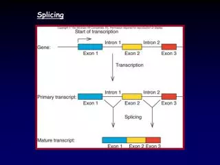
Explore the process of sealing hollow optical fibers with acetylene gas for applications in frequency metrology, atomic clocks, and quantum optics. Learn about splicing challenges and future directions of the project.

E N D
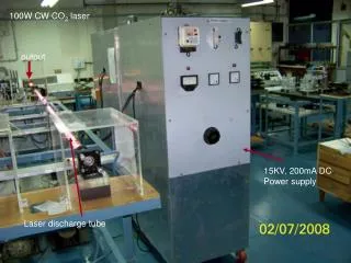
CO2 Laser Fusion Splicing Between PBGF and SMF Dana Cristea Bridgewater College / KSU Physics Research 2006 Other members of LUMOS lab: Kristan Corwin, Rajesh Thapa, Kevin Knabe, Andrew Jones
Purpose • What? ~ Sealing hollow optical fiber containing acetylene gas. • Why? ~ Frequency metrology, atomic clocks and quantum/atom optics • Who else? ~ P.S. Light, F. Couny, and F. Benabid. Single Mode Fiber (SMF) Photonic Bandgap Fiber (PBGF)
My Project Description • Status of Project: - splices made in air; - new apparatus build, untested. • My Goal: - make splices in vacuum. • Results: - Improved splices in air. • Major Challenges: - fiber slipping and sticking to clamps; - fiber length. • Future Directions
Project Set-up HeNe CO2 ZnSe Lens Clamps with Fibers Combiner
ZnSe Lens Lasers are passing through the center of the lens: Lasers are not centered:
Fiber Set-up Power (in mW) = 10 (Power dBm)/10 “Butt Coupled” fibers Fiber connected to Power meter Fiber connected to IR Laser ~2.3dBm (1.69 mW) Clamp on translation stage
Procedure • Secure fibers in clamps • Overlap lasers and align them onto fibers • “Butt Couple” the fibers until maximum transmission obtained. • Apply “Stuffing Stroke” ~ pushing fibers together until transmission drops ~3-4 dBm (fibers shrink during splice).
Splice at 3V for 1 minute or until transmission through fibers drops. Pre-heating for 20 sec. at 0.65V • Activate CO2 laser using Labview program, and observe fiber transmission vs. time. Power Power Drop +1.95 dBm • Calculate Splice Loss. -2.12dBm Splice complete -5.1 dBm Stuffing Stroke Time
Procedure (cont.) • Check splice strength ~ “Break Radius.” BR = (L1+ L2) / (2*π) L1+ L2 =circumference
Challenges • Problem #1: Fiber Slipping during Stuffing Stroke. • Problem #2: Fragile splices. - sticky rubber on clamps - fiber length
ZnSe windows Translation Stage Fixed Clamp ZnSe Lens ZnSe Window
In Vacuum Chamber without ZnSe windows at atmospheric pressure Splice Loss -0.07 dBm => “Perfect” splice With ZnSe windows in Splice Loss +0.55 dBm + 2.235 dBm Break Radius +0.76 cm Break Radius +1.37cm +0.27cm Results
Future of the project • Splice SMF to SMF inside vacuum chamber with air in and lower power. • Splice SMF to SMF with air pumped out. • Splice SMF to PBGF and create acetylene cell.
Special Thanks =) • Dr. Kristan Corwin • Mr. Mike Wells • LUMOS Group (Rajesh Thapa, Kevin Knabe, and Andrew Jones) • Dr. Larry Weaver • NSF/REU/Physics Department • Aaron Pung, Matt Wood, and Greg Johnson