Download
1 / 29
290 likes | 312 Views
This article explores the development of cable-in-conduit conductors for accelerator and fusion applications, highlighting the synergy between the two concepts. It discusses the performance of dipole HF and LF conductors and provides an overview of the ITER project.

E N D
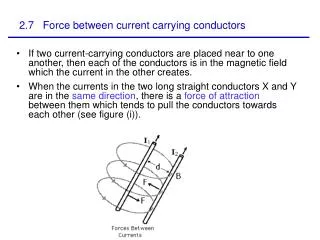
Synergies between Accelerator and Fusion Conductors A. Vostner, S. Bonito-Oliva, A. Portone, H. Rajainmaki and C. SborchiaF4E, ITER Department, Barcelona E. SalpietroEFDA Garching Introduction Cable in conduit conductor development for ITER EFDA dipole: synergy of accelerator and fusion conductor concept Dipole HF conductor: performance vs. void fraction and shape Dipole LF conductor: performance vs. shape and twist pitch Summary
Introduction • The main driver for accelerator and fusion applications are different • Fusion: large volume, energy and required stability • Accelerator: maximisation of current density, field homogeneity • First conductors were flat cables for both type of applications • First accelerator type magnet in late 60’s made of Nb3Sn (W.B. Sampson, BNL) • IMP with silver plated Nb3Sn ribbons (Oak Ridge) in late 60’s • Around 1970 stability issues solved (multifilament, twisting) at RAL → “Rutherford type” cable • T-7 and T-15 with forced flow and flat cable embedded in Cu (Kurchatov, 1970’s), LCT in the 80’s While the cable concept for the accelerator remained unchanged the CICC concept was introduced into fusion in the 80’s Alexander Vostner, 22nd May 2008, WAMSDO 2008, CERN, Geneva
ITER – Magnets System 41 GJ (TF only) vs. 10.5 GJ magnetic energy in the 27 km Tunnel of the Large Hadron Collider at CERN Alexander Vostner, 22nd May 2008, WAMSDO 2008, CERN, Geneva
Fusion – Cable-in-Conduit Main arguments pro CICC • High amperage conductor with large heat removal capability(large ampere turns, acceptable voltages, AC loss, nuclear heat) • Forced flow cooling(only option for large magnets with large stored energy) • High stability (local disturbances and peak loads) • High mechanical strength (outer jacket acts as a structural material) • Flexible design(number of strands, cabling pattern, cooling channel, shape, …) Main arguments contra CICC • Low current density(not a major issue for fusion magnets) • Performance prediction (complex impact of strand/conductor parameters on final performance) Alexander Vostner, 22nd May 2008, WAMSDO 2008, CERN, Geneva
ITER – CICC Development • In 1992 a project was planned under NET to build a coil made of different high amperage Nb3Sn conductors (circular in square, rectangular, braid, twist, …). Activity was stopped due to start of ITER EDA phase. • The early 90’s first circular NET/ITER CICC were tested (40 kA current). • After assessing several options (cabling pattern, conduit material, central channel…) Model Coils (TFMC, CSMC) and Insert coilswere built and tested 2001/2002. [D. Bessette et al., IEEE Trans. Magnetics 30, 2038-2041 (1993)] Alexander Vostner, 22nd May 2008, WAMSDO 2008, CERN, Geneva
ITER TF – TFMC Results Tcs at 80 kA • TFMC exceeded design values • No degradation with cycling • Conductor performance in coil less (~15 %) than expected from single strand or Sultan short sample tests • Degradation shows a BI load dependence → [A. Ulbricht et al., Fus. Eng. Des. 73, 189-327 (2005)] [J.L. Duchateau, CEA] Alexander Vostner, 22nd May 2008, WAMSDO 2008, CERN, Geneva
ITER TF – Conductor • Transverse load (bending) identified as main cause of degradation • Ti-jacket, Ti cooling tube • 588(sc)+924(Cu) strands • 0.7 mm diameter • Braided primary stage (14+15) • 37% void fraction • Solder filled into conductor Bafter reaction • Conductor B performed at expected limit [P. Bruzzone et al., IEEE Trans. Appl. Supercond. 14, 1527-1530 (2004)] Alexander Vostner, 22nd May 2008, WAMSDO 2008, CERN, Geneva
ITER TF – Conductor • Level of degradation depending on strand type (strain sensitivity, irreversible strain limit) but exact dependence not fully understood yet • Updated design with more strands and lower void fraction • First short sample tests in Sultan successful: TFPRO1 (EAS2)(10.78 T, 68 kA) [R. Wesche, CRPP] Alexander Vostner, 22nd May 2008, WAMSDO 2008, CERN, Geneva
ITER TF – Conductor • Cable twist pitch length specification increased after TFPRO2 result: OST2:28.5 % void fraction long twist pitchesOST1:30 % void fraction reference twist pitch • OST2 shows outstanding performance • OST1 and OST2 strands almost identical design • Excellent conductor OST2 uses OST2 strand which shows worse Jc strain behavior • Longer twist pitch lengths and lower void fraction leads to significantly better performance in TFPRO2 → Qualification with final TF spec in 2008 Alexander Vostner, 22nd May 2008, WAMSDO 2008, CERN, Geneva
ITER (TF) Conductor Conclusions • Successful conductor design was developed for the TF coils • CS conductor is being finalised and qualified as well • Performance extrapolation from single strand/subsize conductor is difficult and not reliable: void fraction, twist pitch and strand type play important role for the final conductor performance • Full size conductor tests essential for qualification Alexander Vostner, 22nd May 2008, WAMSDO 2008, CERN, Geneva
Advanced Fusion CICC • Compared to high field HEP conductors the ITER conductors are lessefficient in view of current carrying capability • The main reasons: 1) Fusion type strands have much less Jc than HEP strands (1000 vs. 3000 A/mm2 at 12 T, 4.2 K) 2) Fusion CICC due to thermal mismatch between steel jacket and cable, Jc is reduced by about 50 % (less for CS conductor) 3) Transverse load (bending) on unsupported portions of strand normally adds a degradation of at least 10 % • Some effects are unavoidable (lower conductor Jc due to coolant, copper for protection and jacket) but improvements are possible… Alexander Vostner, 22nd May 2008, WAMSDO 2008, CERN, Geneva
Attempt to merge accelerator and fusion conductor concepts: The EFDA Dipole Conductors Alexander Vostner, 22nd May 2008, WAMSDO 2008, CERN, Geneva
Advanced CICC Design In order to improve performance, we can combine accelerator and fusion conductor technology • Following the Nb3Sn strand development in HEP (high Jc with smaller filaments) a CICC was designed and tested for the EFDA dipole project. • The combination of high Jc strands and CICC provides a conductor design with high current density, stability and cooling power. • Intrinsic instability of high Jc strands is stabilised by direct cooling. • The high performance strands (Jc~ 2500 A/mm2 at 12 T and 4.2 K) have a similar Jc vs. strain dependence but are more prone to bending strain (A. Nijhuis, Twente University). Parameters such as void fraction and twist pitch must be properly selected to obtain a robust conductor design Alexander Vostner, 22nd May 2008, WAMSDO 2008, CERN, Geneva
EFDA Dipole [A. Portone et al., presented at MT20, Philadelphia, accepted for publication in IEEE Trans. Appl. Supercond. 18] Alexander Vostner, 22nd May 2008, WAMSDO 2008, CERN, Geneva
EFDA Dipole – High Field • Based on successful dipole pre-prototype results1, the dipole conductors were designed • Initial performance was lower than expected but acceptable • Continuous degradation with cycling • Explanation: neither cumulative nor single strand load were criticalstrand support? 1[P. Bruzzone et al., IEEE Trans. Appl. Supercond. 16, 894-897 (2006)] Alexander Vostner, 22nd May 2008, WAMSDO 2008, CERN, Geneva
increase of strand support HF Sample 2 EFDA Dipole – High Field • Void fraction and twist pitches were based on typical values as used in fusion CICC • Continuous degradation with cycling is a clear sign of filament cracking due to excessive transverse load HF Sample 1(test without solder) Identical cable was tested in a flatter conductor and with a lower void fraction of 30 %→ [A. Vostner et al., presented at MT20, Philadelphia, accepted for publication in IEEE Trans. Appl. Supercond. 18] Alexander Vostner, 22nd May 2008, WAMSDO 2008, CERN, Geneva
EFDA Dipole – High Field • Max non Cu Jc: 1080 A/mm2 Dipole Jc,op: 460 A/mm2 (12.7 T) ITER Jc,op: 286 A/mm2 (11 T) • Max Cable Jc: 540 A/mm2 Dipole cable Jc,op: 230 A/mm2 (12.7 T)[ITER cable Jc,op: 53 A/mm2 (11 T)] • Operating single strand load: dipole: 2.3 kN/m ITER: 0.9 kN/m • Cycling up to 30 (and 40) kA With these modifications the conductor worked as expected from single strand extrapolation Alexander Vostner, 22nd May 2008, WAMSDO 2008, CERN, Geneva
EFDA Dipole – Low Field LOW FIELD CONDUCTOR • First LF test sample showed same behavior as the HF conductor sample: severe degradation with cycling • Following the successful test of the HF conductor, the void fraction was reduced for the square LF as well. • Shape (square), cable (twist pitch) and jacket remained identical. Only the compaction was increased. Alexander Vostner, 22nd May 2008, WAMSDO 2008, CERN, Geneva
EFDA Dipole – Low Field • Initial performance 20 % below model expectation (i.e. 0.5 – 0.6 K) • After 1000 cycles at 8 T steady state performance with further loss of ~15 % • Single strand load 2.83 kN/m! 0H = 8 T • Significant improvement compared to the first LF sample (void fraction ~37 %) • Performance ok (Bmax of LF2 ~7.8 T) but NOT as good as the HF conductor → Void fraction is a critical parameter but not the only one Alexander Vostner, 22nd May 2008, WAMSDO 2008, CERN, Geneva
EFDA Dipole – Low Field • As demonstrated by last series of ITER TF conductor samples and the dipole HF samples, twist pitch and conductor shape have a significant impact as well. • Small (and fast) R&D activity to address this issue. As strand, the EFDA dipole strand (OST) was used as the strand is more sensitive to bending than other available strands so that the effect should be larger. • As conductor the EFDA dipole LF was selected (all parts available and easier sample manufacture) • Test series covers: -) 3 different twist pitches but identical conductor shape and void fraction -) 2 different shapes but identical cable and void fraction EFDA dipole LF conductor(12.6 x 12.6 mm) Alexander Vostner, 22nd May 2008, WAMSDO 2008, CERN, Geneva
EFDA Dipole – Low Field Reference TP Reference TP Short/Long TP Alexander Vostner, 22nd May 2008, WAMSDO 2008, CERN, Geneva
Low Field – Pitsam5 • Long TP much better from the beginning • Less degradation with cycling for Long TP • Difference in Tcs after cycling ~1 K • Severe degradation of Short TP after warm up cycle [P. Bruzzone, CRPP] Long TP much better performance than Short TP Alexander Vostner, 22nd May 2008, WAMSDO 2008, CERN, Geneva
Twist Pitch – Short vs. Long • PITSAM3 reference TPrectangular (1.5) • PITSAM5 LTP first 3 stages like ITER TF (long)square • PITSAM2 reference TPsquare • PITSAM5 STP first stage 33 mmsquare [P. Bruzzone, CRPP] Performance “scales” with twist pitches but rectangular shape has similar effect than long twist pitch Alexander Vostner, 22nd May 2008, WAMSDO 2008, CERN, Geneva
Strand vs. Conductor • Extrapolation from single strand data • “Equivalent” longitudinal strain: -0.65 % • PITSAM5 Short TP Initial value: 75 % After cycling: 60 % After warm up: 50 % • PITSAM2 Reference TP Initial value: 82 % After cycling: 70 % After warm up: n.m. • PITSAM5 Long TP Initial value: 90 % After cycling: 78 % After warm up: 75 % • PITSAM3 Reference TP (rectangular) Initial value: 85 % After cycling: 82 % After warm up: 75 % Same performance achieved with two different approaches Performance of Long TP rectangular conductor? Alexander Vostner, 22nd May 2008, WAMSDO 2008, CERN, Geneva
Dipole Conductors Conclusions 1/2 • Even with a high Jc strands it is possible to design a successful CICC with steel jacket • For this type and size of strand and conductor 1) lower void fraction 2) long twist pitch 3) rectangular shape significantly improves the conductor performance. • All three parameters increase strand support. • Rectangular shape “generates” similar effect as longer twist pitch Alexander Vostner, 22nd May 2008, WAMSDO 2008, CERN, Geneva
Dipole Conductors Conclusions 2/2 • These effects may be less important for strands with higher bending tolerance (e.g. TFPRO1) • Dipole conductor (144 strands) is much smaller than ITER conductors but demonstrates the potential of Nb3Sn conductors • Next step in progress: NHFML Tallahassee will test a CICC conductor 3 x bigger than the EFDA HF dipole using identical strand, same void fraction and similar elm pressure Alexander Vostner, 22nd May 2008, WAMSDO 2008, CERN, Geneva
Drawbacks Reduction of void fraction reduces cooling capacity (higher pressure drop) and increases AC losses Dipole conductor design improvements not applicable to all conductor types (e.g. ITER CS conductor) Alexander Vostner, 22nd May 2008, WAMSDO 2008, CERN, Geneva
Summary • Fusion magnets use cable in conduit conductors • Advantages are: large energy margin low AC losses high mechanical strength • Disadvantages are: unsupported cable thermal mismatch (with steel) lower current density • Using high Jc strand, lower void fraction and longer twist pitch can mitigate most of the disadvantages • This has been implemented into the dipole (and ITER) conductors • Future: 1) use lower thermal contraction material for the jacket 2) cable size scale up towards dimensions relevant fusion magnets Is the CICC concept applicable to large high field HEP magnets? Alexander Vostner, 22nd May 2008, WAMSDO 2008, CERN, Geneva
Acknowledgement • P. Bruzzone, B. Stepanov, R. Wesche (CRPP Villigen) • A. della Corte, U. Besi-Vetrella (ENEA Frascati) • A. Baldini, M. Cervasio, G. Masciarelli (Luvata Fornaci di Barga) • D. Bessette, A. Devred (ITER IO Cadarache) • J.L. Duchateau (CEA Cadarache) Alexander Vostner, 22nd May 2008, WAMSDO 2008, CERN, Geneva