Download
1 / 45
470 likes | 700 Views
Explore cost-effective heat integration approaches using Heat Exchanger Networks (HEN) to minimize utilities and enhance energy efficiency in industrial processes. Learn optimization methods and key principles for operating and designing efficient heat exchange systems.

E N D
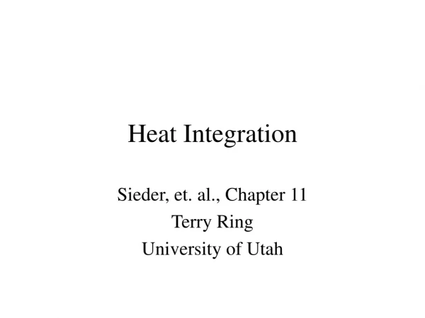
Heat Integration Sieder, et. al., Chapter 11 Terry Ring University of Utah
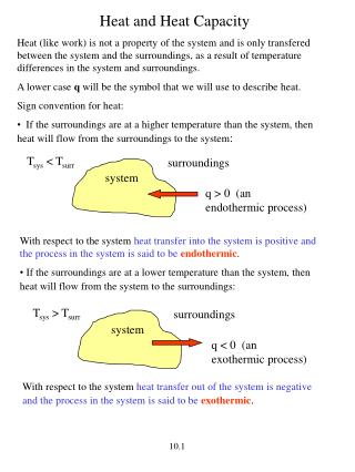
Lost Work = Lost Money • Transfer Heat from T1 toT2 • ΔT [= T1-T2] approach Temp. for Heat Exchanger • To= Temperature of Environment • Use 1st and 2nd laws of Thermodynamics • ΔT • LW=QTo(T1-T2)/(T1T2) • Q= UoAΔTlm =UoA(ΔT1-ΔT2)/ln(ΔT1/ΔT2) T1 Q T2
Costs • Heat Exchanger Purchase Cost (Inside BL) • Cp,i=K(Areai)0.6 • Area= Q/UoΔTlm • Annual Cost • CA=im[ΣCp,i+ ΣCP,A,j]+(s)Fs+(cw)Fcw • im=return on investment • Fs= Annual Flow of Steam, • $13.2/Tonne to $17.6/Tonne = s • Fcw=Annual Flow of Cold Water • $0.027/m3 =$0.027/Tonne = cw Auxiliary HX outside BL
Heat Integration • Make list of HX • Instead of using utilities can you use another stream to heat/cool any streams? • How much of this can you do without causing operational problems? • Can you use air to cool? • Air is a low cost coolant. • Less utilities = smaller cost of operations
Ultra-high purity Si plant design Si at 99.97% Powder H2 & HCl Separation Train Fluid Bed Reactor (400-900C) Si+7HCl SiHCl3 + SiCl4 +3H2 Si+ 2HCl SiH2Cl2 Flash HCl SiCl4 H2-HCl Separation HCl H2 SiCl4 Very Pure SiHCl3&SiH2Cl2 Fluid Bed Reactor(600C) Si+SiCl4+2HCl 2SiHCl3 Flash Reactor (1200C) SiHCl3+H2 Si+3HCl SiH2Cl2+1/2 H2 Si+3HCl Si H2 HCl Si at 99.999999999%
Terms • HEN=Heat Exchanger Network • MER=Maximum Energy Recovery • Minimum Number of Heat Exchangers • Threshold Approach Temperature • Optimum Approach Temperature
Minimize UtilitiesFor 4 Streams 470 480
Minimize UtilitiesFor 4 Streams 470 480
Pinch Analysis1) Adjust Hot Stream Temperatures to Give ΔTmin=10°F 2) Order T’s, 250, 240, 235, 180, 150, 120
Pinch Analysis1) Adjust Hot Stream Temperatures to Give ΔTmin Order T’s, 250, 240, 235, 180, 150, 120
Pinch AnalysisMinimum Utilities =ΔHi+50
Pinch AnalysisMinimum Utilities =ΔHi+50
Pinch Analysis Actual Endpoint Temperatures! ΔTapp MER values
How to combine hot with cold? • Big Exhangers 1st • 1st HX at Pinch (temp touching pinch) • Above Pinch Connect • Cc≥Ch • Below Pinch Connect • Ch≥Cc • 2nd Hx or not touching Pinch temp. • No requirement for Cc or Ch
Pinch Analysis Actual Endpoint Temperatures! Cc≥Ch 3*(260-190)=210 1.5*(250-190)=90 2*(235-180)=110 4*(240-180)=240 ΔTapp MER values
Pinch Analysis Actual Endpoint Temperatures! Cc≥Ch 3*(260-190)=210 1.5*(250-190)=90 2*(235-180)=110 90=2*(T-180) T=225 4*(240-180)=240 210=4*(T-180) T=232.5°F ΔTapp 20 30 MER values
How to combine hot with cold? • Big Exhangers 1st • 1st HX at Pinch (temp touching pinch) • Above Pinch Connect • Cc≥Ch • Below Pinch Connect • Ch≥Cc • 2nd Hx or not touching Pinch temp. • No requirement for Cc or Ch
Pinch Analysis Actual Endpoint Temperatures! Ch≥Cc 3*(190-160)=90 1.5*(190-130)=90 30=1.5*(190-T) T=170°F 2*(180-120)=120 90=2*(180-T) T=135°F 2*(135-120)=30 60 ΔTapp MER values
4 Heat ExchangerHEN for Min. Utilities Cc≥Ch Ch≥Cc CW MER Values Steam
Pinch AnalysisMinimum Utilities =ΔHi+50
Comparison Simple HEN HEN with Min. Utilities Saves CW 7.5e4 BTU/hr Steam 7.5e4 BTU/hr
Too Many Heat Exchangers • Sometimes fewer Heat exchangers and increased utilities leads to a lower annual cost • NHx,min= Ns + NU - NNW • s=No. streams • U=No. discrete Utilities • NW=No. independent Networks (1 above the pinch, 1 below the pinch) • Solution to Too Many Heat Exchangers • Break Heat Exchanger Loops • Stream Splitting • Attack small Heat Exchangers First for elimination 4+2-2=4
Stream Splitting 1 • Two streams created from one • one heat exchanger on each split of stream with couplings 1 1b 1a 1b 1a
Example CP=K(Area)0.6
Last Considerations • How will HEN behave during startup? • How will HEN behave during shutdown? • Does HEN lead to unstable or difficult to control plant operations?
Optimization of HEN • How does approach ΔT >ΔTmin effect the total cost of HEN? • Q= UA ΔT • Greater ΔT smaller A • Less capital cost • LW=QToΔT/(T1T2) • Greater ΔT more LW • More Utility cost
ΔTmin • S T(C) T(C) C Q(kW) • H1 300 200 1.5 150 • H2 300 250 2 100 • C1 30 200 1.2 204 ΔTapp=10C ΔTapp=105C LW=QToΔT/(T1T2)
Costs • Heat Exchanger Purchase Cost (Inside BL) • Cp,i=K(Areai)0.6 • Area= Q/UoΔTlm • Annual Cost • CA=im[ΣCp,i+ ΣCP,A,j]+sFs+(cw)Fcw • im=return on investment • Fs= Annual Flow of Steam, • $13.2/Tonne to $17.6/Tonne = s • Fcw=Annual Flow of Cold Water • $0.027/m3 = cw Auxiliary HX outside BL
Change ΔTmin Area=Q/(UF ΔTmin) CP=K(Area)0.6 More Lost Work LW=QToΔT/(T1T2)