Download
1 / 25
250 likes | 459 Views
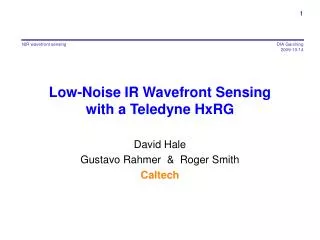
1. Low-Noise IR Wavefront Sensing with a Teledyne HxRG. David Hale Gustavo Rahmer & Roger Smith Caltech. 2. Why a Natural Guide Star for Laser AO?. Wavefront tilt is not seen by a laser guide star, since the laser light retraces its outward path, so…

E N D
1 NIR wavefront sensing Low-Noise IR Wavefront Sensing with a Teledyne HxRG David Hale Gustavo Rahmer & Roger Smith Caltech
2 Why a Natural Guide Star for Laser AO? NIR wavefront sensing • Wavefront tilt is not seen by a laser guide star, since the laser light retraces its outward path, so… • The TMT/IRIS OIWFS will use three natural guide stars to measure tilt, rotation and scale changes. • The brightest guide star will pass through a 2×2 Shack-Hartmann sensor to measure focus and astigmatism. • Each of three probes can be reconfigured on the fly to be either TT only, or TTFA
Why the NIR ? NIR wavefront sensing Goal:increase fraction of sky over which adequate AO performance is achieved. • Need to guide on AO corrected image to close the tilt loop. • Need NIR to get good Strehl and thus adequate tilt sensitivity. • The most common stars are brightest in the NIR. • Diffraction core of 30m telescope is so small that background per pixel is negligible in J+H band • Although Strehl is better for K band, sky is much brighter and diffraction core is larger
Some Detector Options Considered NIR wavefront sensing • Intevac: electron bombarded CCD with InGaAs photocathode. • Dark current way too high and uncontrolled • >100 Hz frame rates not available (until CCD upgraded to CMOS imager) due to ROI overheads • Current format not ideal (1024×256) • HgCdTe APD arrays: • Attractive promises, but not ready enough yet • HxRG • Well understood • Large format • High QE. • Noise on recent devices good enough after multiple sampling.
5 Format (not to scale) NIR wavefront sensing • Current baseline is ~ 1K×1K operable region within H2RG rather than H1RG, since Teledyne advises this will be no more expensive and that the H1RG may be discontinued. • Size of capture region is set by seeing and probe positioning accuracy • Spot will be small when high order correction is turned on, moving on scale of seeing profile until low order loop closed. • Final guide window size may be as large as 14×14 pixels to handle impulse perturbations. H2RG Capture region ~ 1k × 1k 2048 14×14 recapture window 4×4 guide window 2 mas/pix 2 arcsec 2048
Zoom to Capture NIR wavefront sensing • Start with seeing limited image (>1/4 detector area) • Big, fuzzy, low contrast. • Move to center by adjusting probe position or telescope pointing. • Turn on high order correction. • Tiny spot scribbles lines over the seeing profile. Not much change seen in long exposure. • Window down on seeing limited image. • Faster frame rate makes wiggly line shorter. • Close loop at low gain to drive centroid towards center of window. • Steadily reduce window size to increase frame rate and loop gain. • Servo keeps spot within shrinking window. • Zoom in to 4×4 window • avoid bad or noisy pixels
Why Such a Big Detector? (… justto replace a quad cell !) NIR wavefront sensing • Big telescope aperture makes tiny diffraction core: FWHM = /D = 0.008 arcsec at 1.2µm • Quad cell requires ~0.004 arcsec/pixel • Prefer 0.002 arcsec/pixel so that positioning on pixel boundary not required to maximize centroiding sensitivity. • 2 arcsec field of view needed to capture seeing profile. We could go larger to aid acquisition. Thus need >1K2 • Freebie: science image can be acquired around guide star, since H2RG allows nested windows and independent reset.
Maximizing Frame Rate NIR wavefront sensing • The spot is compact throughout the zoom, since laser guide star sensor is blind to tip tilt, but it is smeared by image motion. • Our problem is to locate it (short frame time) and • Measure tilt accurately (low noise) to feed back to servo. • Flux per pixel depends on image motion rather than exposure time, so maximize frame rate. • Pixel time has been minimized. • For window >64 pixels: 32 ch readout, skipping unwanted lines. • For window <64 pixels: single channel, window mode. • By 64×64, frame rate = 50Hz … tilt error already << window size. • Readout time = (5.16*N2 +10.33*N + 5.28) µs = 21.8ms • For fainter guide stars final rate ~100Hz. For frames <44×44, can use multiple sampling to reduce the read noise below the ~11 e- for CDS. • For brighter guide stars final rate ~800 Hz, with less noise averaging.
Begin multiple sampling here Noise & Frame Rate During Zoom NIR wavefront sensing NIR wavefront sensing Bright stars Faint stars Start zoom Big frames, CDS noise 4x4 1024x1024
Let’s review common readout timing options…. Ignore p scans Reset while idling Correlated Double Sampling NIR wavefront sensing e = 1 = number of exposures to do …. not shown here r = number of reset scans between exposures m = 1 = number of scans to coadd then store. p = 10 = number of dummy scans between coadded groups k = 2 = number of store cycles per exposure • Exposure delay = p dummy reads for constant self heating • Subtract first frame from last frame • Equivalent to Fowler sampling with m = 1 Frame time Exposure time At least one reset between frames Final scan Initial scan
Coadd m Ignore p scans Coadd m Fowler “m” NIR wavefront sensing e = 1 = number of exposures to do …. not shown here r = number of reset scans between exposures m = 3 = number of scans to coadd then store. p = 6 = number of dummy scans between coadded groups k = 2 = number of store cycles per exposure Duty cycle < 1 • Exposure delay is in units of full scan ties but need not be multiple of m. • Subtract mean of first group from mean of last group. Frame time Exposure time
Sample up the ramp. NIR wavefront sensing e = 1 = number of exposures to do …. not shown here r = number of reset scans between exposures m = 1 = number of scans to coadd then store. p = 0 = number of dummy scans between coadded groups k = 12 = number of stores per exposure • Store every scan (no real time coadd) • Use post facto least squares fit to measure slope with best S/N; • Effective exposure duty cycle due to weighting of shot noise by least squares ~ 90%; reduce this to include effect of the reset overhead. • Equivalent MultiAccumulate with m=1.
Coadd m Coadd m Coadd m Coadd m Coadd m Reset r scans Multi-Accumulate (JWST terminology) NIR wavefront sensing e = number of exposures to do …. not shown here r = 2 = number of reset scans between exposures m = 3 = number of scans to coadd then store. p = 0 = number of dummy scans between coadded groups k = 4 = number of stores per exposure • Coadd in real time, store every m scans, total exposure duration is multiple of m scan times. • Least squares fit of stored (coadded) scans is used to estimate noise. • Advantage of coadd over single samples with gaps is lower noise and better cosmic ray detection ( which appears as jump in ramp). • One or more reset scans between exposures.
Coadd m Coadd m Coadd m Coadd m Coadd m Coadd m Proposed mode for OIWFS (used in the noise tests presented here)Differential Multi-Accumulate NIR wavefront sensing Exposure time • Using previous frame as baseline for next frame (without reset) makes duty cycle ~100%, except for a gap when reset occurs. • Gaps at time of reset can be reduced in duration by using single scan or significantly fewer scans to establish first baseline instead of averaging m scans. This will produce a noisier result instead of a missing result. Which is better? • The reset scan and initial read scan can be combined so the reset time is hidden. Reset Difference = frame 4 Occasional gap ! Difference = frame 1 Difference = frame 2 Difference = frame 3
Nested Windows NIR wavefront sensing • TMT operates at such a fine plate scale that there is concern over loss of lock of the tip tilt servo due to imperfections in the M3 bearing. • Nested windows: multiple sample small guide window, then CDS read surrounding window during the exposure delay for the small window. • Thus if the spot jumps out of the guide window we can get a snapshot just half a frame time later…
coadd coadd coadd coadd Nested Windows NIR wavefront sensing subtract subtract subtract • Read a 4x4 window multiple times and coadd to beat down noise. • Read surrounding, larger window once, then revert to small window. • Calculate differences of (coadds of) small windows and differences of large windows separately. • Exposure times for each window size are same (though offset by half an exposure time). Noise is lower for the central 4x4 window since it is sampled more often. • Size of the large window depends on frame rate and fraction of time allocated to big window as opposed to beating down the noise in the 2x2 window. • If 50% of time is allocated to the larger window at 100 Hz, it can be 31 pixels across with 11 e- read noise, or a 14 pixel window can be read five times reducing read noise to ~5e-. subtract subtract subtract
Higher CDS noise Noise vs. Frame Rate measured for various frame sizes NIR wavefront sensing NIR wavefront sensing Desired 100Hz operating point gives <3e- read noise for 4×4 window. Latest low noise 2.5µm recipe Why this bump? • Mean noise for all pixels in window. • Negligible dark current at 80K. Why these turn-ups?
20 “Dark Signal” (…mentioned in Roger’s talk this morning) NIR wavefront sensing Slope depends on number of reads per pixel, not time 0.0034 e- / read for 6µs pixel
Noise vs. Frame Rate measured for various frame sizes NIR wavefront sensing NIR wavefront sensing Latest low noise 2.5µm recipe
“Dark Signal” Effect on Measured Noise NIR wavefront sensing NIR wavefront sensing • The small turn-ups are caused by the “dark signal” • Subtracting mean effect leaves us with 1/f noise But… • still have the “bump” and the unexplained large turn-up at very low frequencies Latest low noise 2.5µm recipe Still have these… Just 1/f noise
2×2 Window NIR wavefront sensing NIR wavefront sensing Latest low noise 2.5µm recipe Individual pixels in the 2×2 window … mean was contaminated by noisy pixels CDS noise is poor predictor of final noise floor !
64×64 Window NIR wavefront sensing NIR wavefront sensing Latest low noise 2.5µm recipe Hot pixels
Tip-Tilt Wavefront Error NIR wavefront sensing • Median WFE 26.3 nm Read noise contours • Zero read noise device needs QE ≥ 65% to be as good as H2RG • Neither QE nor noise improvements offer significant WFE reduction in this regime Demonstrated: 2.8e- @ 80Hz, 4×4 window >80% QE
Sky Coverage Analysis NIR wavefront sensing Requirements: • 2mas jitter @ 50% Exceeded, ~90% sky coverage 2mas
The End NIR wavefront sensing Let’s party !