Download
1 / 20
660 likes | 2.21k Views
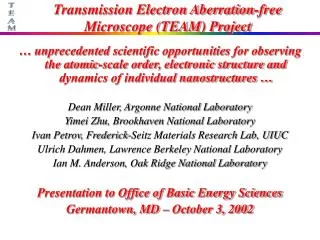
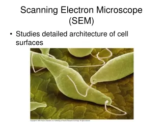
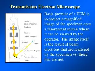
Transmission Electron Microscope. Basic premise of a TEM is to project a magnified image of the specimen onto a fluorescent screen where it can be viewed by the operator. The image itself is the result of beam electrons that are scattered by the specimen vs. those that are not.

E N D
Transmission Electron Microscope Basic premise of a TEM is to project a magnified image of the specimen onto a fluorescent screen where it can be viewed by the operator. The image itself is the result of beam electrons that are scattered by the specimen vs. those that are not.
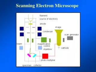
A simplified ray diagram of a TEM consists of an electron source, condenser lens with aperture, specimen, objective lens with aperture, projector lens and fluorescent screen.
In actuality a modern TEM consists of many more components including a dual condenser system, stigmators, deflector coils, and a combination intermediate and dual projector lens.
Total magnification in the TEM is a combination of the magnification from the objective lens times the magnification of the intermediate lens times the magnification of the projector lens. Each of which is capable of approximately 100X. Mob X Mint X Mproj = Total Mag
Under different conditions of high and low magnification the same component can have different functions
Depth of Field: the range of distance at the specimen parallel to the illuminating beam in which the object appears to be in focus. Depth of Focus: the range of distance at the image plane (i.e. the eyepiece, camera, or photographic plate) in which a well focussed object appears to be in focus.
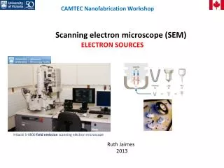
Condenser lens The role of the condenser lenses is to make the beam that is striking the specimen as nearly parallel as is possible
As magnification increases the condenser lens must be adjusted to properly illuminate the specimen. When the lens is brought to its smallest spot the beam is said to be at the crossover point
Holey (not Holy) Formvar is used to critically adjust the stigmation of a TEM. When the beam is under or over focused on the specimen a Fresnel fringe becomes visible due to the effects of diffraction around the edges of the whole. When this Fresnel fringe is evenly distributed then the beam is said to be stigmated.
Deflection Coils In older TEMs functions such as gun and beam alignment were accomplished by physically moving components in the column. Today they are achieved by use of electromagnetic deflection coils that are positioned throughout the column
Using the deflection coils the beam can be shifted so that the focused beam is centered in the back focal plane of the lens and tilted so that the beam is centered on the specimen.
We call these centering spots “pivot points” and as the beam is shifted or tilted back and forth there should be no apparent movement if the scope is properly aligned
Likewise the position of the specimen relative to the beam is of critical importance. To adjust the height or “Z” position of the specimen it is physically rocked back and forth until an object in the center no longer moves
A major problem with TEM lens design is the fact that there is very little space between the pole pieces of the objective lens to accommodate the specimen and objective aperture. This also puts severe constraints on how far the specimen can be tilted within the lens.
A clever solution to this problem came in the invention of the double objective or “twin” lens. In this lens design the specimen actually lies between two separate lens fields allowing for tilt angles as large a 60o from perpendicular to the optical axis
Focus Wobbler Shifts the image back and forth, and when the movement is stable the image is focused
Focus Wobbler Shifts the image back and forth, and when the movement is stable the image is focused
Focus Wobbler Shifts the image back and forth, and when the movement is stable the image is focused
The depth of focus is so great for the projector lens system that an image that is in focus on the screen will also be in focus on plate film beneath the screen or even a TV chip below the plate film