Download
1 / 26
260 likes | 719 Views
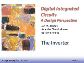
Integrated Circuit Design Lecture 11 (this lecture adopted from © 2002 Prentice Hall). Seungjun Lee Information Electronics Eng. Ewha Womans University. In This Lecture. Combinational Logic Design Static CMOS design Complementary CMOS Ratioed Logic Pass-Transistor Logic

E N D
Integrated Circuit DesignLecture 11(this lecture adopted from © 2002 Prentice Hall) Seungjun Lee Information Electronics Eng. Ewha Womans University
In This Lecture • Combinational Logic Design • Static CMOS design • Complementary CMOS • Ratioed Logic • Pass-Transistor Logic • Dynamic CMOS design (Chap. 6.3) • Dynamic CMOS • Charge sharing • Domino logic • NORA logic
Static CMOS – Complementary F(In1,In2,In3) = G(In1,In2,In3)
Dynamic CMOS • In static circuits at every point in time (except when switching) the output is connected to either GND or VDD via a low resistance path. • fan-in of n requires 2n (n N-type + n P-type) devices in case of complementary CMOS logic • Dynamic circuits rely on the temporary storage of signal values on the capacitance. • requires on n + 2 (n+1 N-type + 1 P-type) transistors • requires ‘clock’ signal in addition to input signals
Clk Mp Out A C B Clk Me Dynamic Gate Out = ((AB)+C) Prech on 1 0 Clk Out 0 off
Clk Mp Out ((AB)+C) A C B Clk Me Dynamic Gate Out = ((AB)+C) 1 off Prech Eval Clk Out on 1
Clk Mp Out A C B Clk Me Dynamic Gate Out = ((AB)+C) Prech on 1 Eval Prech 0 Clk Out 0 off
Properties of Output at Evaluate • Once the output of a dynamic gate is discharged, it cannot be charged again until the next precharge operation. • Inputs to the gate can make at most one transition during evaluation. • Output is in the high impedance(high-Z) state during evaluation if PDN is turned off. The state(data) is stored on CL
Properties of Dynamic Gates • Logic function is implemented by the PDN only • number of transistors is N + 2 (versus 2N for static complementary CMOS) • Full swing outputs (VOL = GND and VOH = VDD) • Non-ratioed - sizing of the devices does not affect the logic levels • Faster switching speeds • reduced load capacitance due to smaller output loading (NMOS only) • no short circuit current - all the current provided by PDN contributes to discharging CL
Properties of Dynamic Gates • Overall power dissipation usually higher than static CMOS • no static current path ever exists between VDD and GND (including short-circuit current during transition) • higher transition probabilities • extra load on Clk • PDN starts to work as soon as the input signals exceed VTn, so VM, VIH and VIL equal to VTn • low noise margin: NML≈ VTn • Needs a clock for precharge/evaluate
CL Issues in Dynamic Design 1: Charge Leakage CLK Clk Mp Out A Evaluate VOut Clk Me Precharge Leakage sources • Output voltage may decrease during evaluate due to leakage current. • Dynamic circuits requires minimal clock rate. (~ a few KHz)
CL Solution to Charge Leakage Small PMOS as a Keeper Clk Mp Mkp Out A Out B Clk Me • Same approach as level-restorer for pass-transistor logic
CL CA CB Issues in Dynamic Design 2: Charge Sharing • Out node is set to ‘1’ during precharge. • It is supposed to stay at ‘1’ during ‘evaluate’ when A =1 and B = 0. • Charge stored originally on CL is redistributed (shared) over CL and CA • It leads to reduced voltage level at Out node. Clk Mp Out A B=0 Clk Me
Voltage Drop due to Charge Sharing V DD M Clk p Out C L M A a X C a M = B 0 b C b M Clk e
Example: V DD • VDD = 5V, VTN = 0.6V, CL = 50fF, Ca = 20fF • Vout = 5 * 50/(50+20) = 3.57V • ΔVout = 1.43V => case 2 • VDD = 5V, VTN = 0.6V, CL = 50fF, Ca = 5fF • Vout = 5*50/(50+5) = 4.54V • ΔVout = 0.46V < VTN => case 1 • VX = 4.54V (not possible!) • VX,max≈ 4.4V (= VDD – VTN) • Vout =(CL*VDD – CaVx)/CL = 4.56V M Clk p Out C L M A a X C a M = B 0 b C b M Clk e
Solution to Charge Redistribution Clk Clk Mp Mkp Out A B Clk Me Precharge internal nodes using a clock-driven transistor (at the cost of increased area and power)
CL1 CL2 Issues in Dynamic Design 3: Capacitive Coupling Clk Mp Out1 =1 Out2 =0 In A=0 B=0 Clk Me Dynamic NAND Static NAND
Out1 Voltage Clk Out2 In Time, ns Backgate Coupling Effect May turns on the PMOS in the second gate => static current!
CL Issues in Dynamic Design 4: Clock Feedthrough Coupling between Out and Clk input of the precharge device due to the gate to drain capacitance. So voltage of Out can rise above VDD. The fast rising (and falling edges) of the clock couple to Out. Clk Mp Out A B Clk Me
Clock Feedthrough Clock feedthrough Clk Out In1 In2 In3 In & Clk Voltage In4 Out Clk Time, ns Clock feedthrough
Clk In Out1 V Out2 Cascading Dynamic Gates V Clk Clk Mp Mp Out2 Out1 In Clk Clk Me Me VTN t Only 0 1 transitions allowed at inputs!
Domino Logic Clk Mp Clk Mp Out1 Out2 1 1 1 0 0 0 0 1 In1 In4 PDN In2 PDN In5 In3 Clk Me Clk Me
Ini Ini Ini Ini PDN PDN PDN PDN Inj Inj Inj Inj Why Domino? Clk Clk • Like falling dominos! • Only non-inverting logic can be implemented. • -> rarely used nowadays
Differential (Dual Rail) Domino off on Clk Clk Mp Mkp Mkp Mp Out = AB Out = AB 1 0 1 0 A A B B Clk Me Solves the problem of non-inverting logic
np-CMOS Clk Me Clk Mp Out1 1 1 1 0 In4 PUN In1 In5 In2 PDN 0 0 0 1 In3 Out2 (to PDN) Clk Mp Clk Me Only 0 1 transitions allowed at inputs of PDN Only 1 0 transitions allowed at inputs of PUN