Download
1 / 21
210 likes | 234 Views
Explore channel characteristics in USR scenarios for ticket gate-to-smartphone communication. Analyze signal distribution, power delay profile, and frequency response with metal and non-metal plates. Understand delay spread and power ratio variations for enhanced connectivity models.

E N D
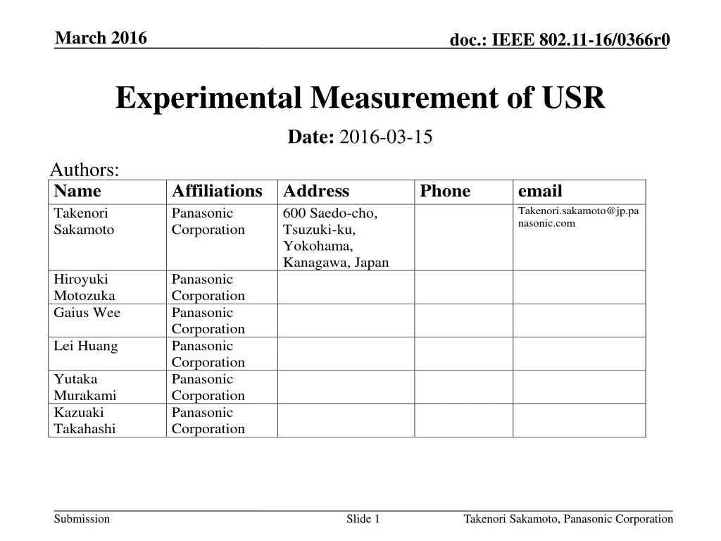
Takenori Sakamoto, Panasonic Corporation Experimental Measurement of USR Authors: • Date: 2016-03-15
Takenori Sakamoto, Panasonic Corporation Abstract Train Station • The IEEE 802.11ay group proposed the Ultra Short Range (USR) communication as one of the use cases[1]. • In this presentation, we considered the communication between the ticket gate and the smart phone as an example of USR scenario and measured the channel characteristics. • The purpose of this presentation is a contribution toward developing a model of USR scenario in Channel Model Document[2]. Video/audio clip, magazine, newspaper, etc.
Takenori Sakamoto, Panasonic Corporation Measurement Methodology • 2-port network analyzer in 56.28~66.84GHz was used. • In the experiments, 7.43dBi antenna were used as Tx and Rx antennas. • To confirm the effect of reflection, metal or non-metal plates were attached to Tx antenna and Rx antenna. • Metal plate : to get basic characteristics • Non-metal plate : actual product • The S-parameters (S21) were measured by changing Rx antenna position.
Takenori Sakamoto, Panasonic Corporation Measurement Setup Tx/Rx Antenna Tx (Ticket gate) Plastic stay Plastic stay Rx (Smart Phone) X,Y,Z axis and Measuring Position Styrofoam stand Plate
Takenori Sakamoto, Panasonic Corporation Plate Size and Antenna Position (There are holes in front of the antennas.) Thickness : 2mm
Takenori Sakamoto, Panasonic Corporation Antenna Specification • Type : Horn • Gain (Directivity) : 7.43dBi • 3dB beam width (E-plane) : 133.3deg. • 3dB beam width (H-plane) : 83.2deg.
Takenori Sakamoto, Panasonic Corporation Measurement Conditions
Takenori Sakamoto, Panasonic Corporation Measured Received Power Distribution • When the metal plates are attached, the received power distributes in the form of the metal plateof the smart phone. • When the non-metal plates are attached, the distribution is concentric. Smart Phone
Takenori Sakamoto, Panasonic Corporation 1D Distribution of Measured Received Power Horizontal Vertical Horizontal Vertical
Takenori Sakamoto, Panasonic Corporation Measured Power Delay Profile • The first peak of the profile is the direct ray. • When the metal plates are attached, there are several peaks at nearly equal interval of about 0.7ns after the first peak. These peaks are multiple reflected rays. The multiple reflected rays show the drastic decrease at the time of about 5ns, because 7th multiple reflected ray does not reflect from the metal plate due to its limited size at 10cm distance. So, the number of the major multiple reflected rays depends on the communication distance and the plate size. • When the non-metal plates are attached, since the rays penetrate the plate, there are few multiple reflected rays. Direct ray 0.7ns Multiple reflected rays 1st 2nd 3rd 4th 5th 6th 7th
Takenori Sakamoto, Panasonic Corporation Measured Power Delay Profile (Cont’d) • X=10cm, Y=0cm, Z=0cm Direct 1st multiple reflected 2nd multiple reflected Free space path loss Metal plate Attenuation relative to free space path loss Because the plates have a hole at the antenna position, maybe reflection coefficient is smaller than metal plate. non-Metal plate
Takenori Sakamoto, Panasonic Corporation Measured Power Delay Profile (Cont’d) • X=10cm, Y=5cm, Z=0cm reflect from metal plates reflect from plastic stay and metal plate Attenuation relative to free space path loss
Takenori Sakamoto, Panasonic Corporation Measured Power Delay Profile (Cont’d) • X=10cm, Y=0cm, Z=5cm reflect from metal plates reflect from antenna and metal plates Attenuation relative to free space path loss
Takenori Sakamoto, Panasonic Corporation Measured Power Delay Profile (Cont’d) • X=10cm, Y=0cm, Z=-5cm reflect from plastic stay and metal plate Attenuation relative to free space path loss
Takenori Sakamoto, Panasonic Corporation Channel Frequency Response • Frequency selective fading is observed, when the metal plates are attached. • Depending on the position of the receiver, the fading can be deep.
Takenori Sakamoto, Panasonic Corporation RMS Delay Spread Distribution • The delay spread distribute concentrically. • Due to the multiple reflected rays between the metal plates, relatively long delay spreads were observed. Relatively long delay spread
Takenori Sakamoto, Panasonic Corporation CDF for RMS Delay Spread • Delay Spread • 0.34ns~1.4ns (Metal plate) • 0.23ns~0.91ns (Non-Metal plate)
Takenori Sakamoto, Panasonic Corporation Peak to Total Power Ratio (PTPR) Distribution • PTPR = 10×log(Ppeak/Ptotal) • The PTPR distributes concentrically. • When the metal plates were attached, due to the multiple reflected rays, low PTPR was observed. Small PTPR
Takenori Sakamoto, Panasonic Corporation CDF for PTPR • PTPR • -20.8dB~-0.14dB (Metal plate) • -11.5dB~-0.10dB (non-Metal plate) • The difference of minimum PTPR is about 9dB.
Takenori Sakamoto, Panasonic Corporation Conclusion • This work presents the experimental measurement results of USR communication with wide HPBW antenna. • To confirm the effect of reflection between the bodies of the ticket gate and the smart phone, metal and non-metal plates were attached to Tx antenna and Rx antenna. • The delay spread is very short for both metal plate attached antenna and non-metal plate attached antenna. • Theses results of this work should be reflected in USR channel modeling.
Takenori Sakamoto, Panasonic Corporation References • [1] 11-15-0625-03-00ay-ieee-802-11-tgay-usage-scenarios.pptx • [2] 11-15-1150-02-00ay-channel-models-for-ieee-802-11ay.docx