Unified Structural Representation (USR) for Fault System Analysis
The USR project focuses on developing a unified 3D representation of active faults and Earth structure for fault system analysis, ground motion prediction, and hazard assessment. It includes Community Fault Models (CFM, CFM-R) and Community Velocity Models (CVM, CVM-H) among others. Cutting-edge methodologies such as 3D waveform tomography are incorporated to enhance resolution in structure modeling. The latest version, CVM-H 6.0, integrates basin structures and Moho representation for improved simulations. Various seismic hazard studies have utilized USR's advancements.

Unified Structural Representation (USR) for Fault System Analysis
E N D
Presentation Transcript
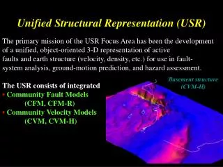
Unified Structural Representation (USR) The primary mission of the USR Focus Area has been the development of a unified, object-oriented 3-D representation of active faults and earth structure (velocity, density, etc.) for use in fault- system analysis, ground-motion prediction, and hazard assessment. The USR consists of integrated • Community Fault Models (CFM, CFM-R) • Community Velocity Models (CVM, CVM-H) Basement structure (CVM-H) Plesch et al., (2007)
SCEC Community Velocity Model (CVM-H) SCEC3 highlights • Version 5.7 available • Updates include: - major basin and fault structures from CFM (Salton, Ventura, Santa Maria, …) - basins embedded in updated tomographic and teleseismic shear wave models - independent Vp and Vs parameterizations - geotechnical layer • Used in strong ground motion & seismic hazards studies in SCEC.
USR has pioneered efforts to develop and implement methods of 3D waveform tomography for improving our resolution of structure, and thus improving strong ground motion simulations Chen, Zhao, & Jordan (2008): F3DT, scattering integral method CVM 3.0 (Vs) LAF3D model Perturbations LAF3D to CVM 9km Tape et al., (2009): Adjoint, spectral element methods CVM-H 3.0 (Vs) Vs model (m16) Perturbations m16 to CVM-H
CVM-H 6.0: integrating 3D waveform inversion results CVM-H 5.8 CVM-H 6.0 0 km depth 5 km depth Moho surface The latest version of the SCEC Community Velocity Model (CVM-H 6.0) includes basin structures embedded in the 3D waveform inversion model of Tape et al. (2009), and an explicit representation of the Moho (after Yan and Clayton, 2007; Chulick and Mooney, 2002).
Broadband Ground Motion Simulation Platform Low Frequency Simulation (< 1 Hz) 1. 1D / 3D GF 2. 3D AWM 3. Site Effects 4. … • Source Description • CFM, ERF • Mw, Dimension, Geometry • … Kinematic Rupture Generator 1. Beroza 2. Archuleta 3. Graves 4. … Combine Low & High Frequency 1. Filters 2. Time Shift 3. … • GF Libraries • Site Lists • Velocity Models • … Standard Rupture Format High Frequency Simulation (> 1 Hz) 1. 1D / Ray GF 2. Scattering 3. Site Effects 4. … Broadband Time Histories (0 – 10 Hz)