Download

1 / 44
440 likes | 460 Views
Testing the mechanism. Step 1 Where will the C 2 attack?. The colours show the range of the attractive potential - green most attractive. The intense region is next to the shifted pentagon and its next neighbouring hexagon towards the tube tip.

E N D
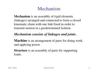
Testing the mechanism Step 1 Where will the C2 attack?
The colours show the range of the attractive potential - green most attractive. The intense region is next to the shifted pentagon and its next neighbouring hexagon towards the tube tip. The favoured attack site for C2 is next to the shifted pentagon.
New mechanism for C2 ingestion • Based on a mechanism proposed by Endo and Kroto in the early 90s for C2 ingestion into nanotube caps / fullerenes. • Mechanism for fullerene/nanotube growth without the aid of catalysts. • New mechanism contains less steps and more stable intermediaries.
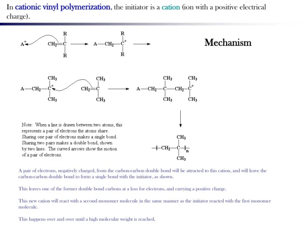
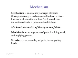
Pentagons blue Heptagons grey Starting with one pentagon displaced Growth mechanism applied to a nanotube tip (other end H terminated) Schlegel diagram shows equivalent for C76
C2 ingestion in fullerenes and nanotube caps Summary of work to date by Chris Ewels, Alberto Zobelli, Greg Van Lier, Harry Kroto
Vertical slice through total electrostatic potential for the tip through the shifted pentagon. The colours show the range of the attractive potential from -0.014 to -0.01 (-0.014 being the most attractive value). The potential exhibits an intense region next to the shifted pentagon and its next neighbouring hexagon towards the tube tip. The favoured attack site for C2 is next to the shifted pentagon.
Vertical slice through total electrostatic potential for the tip through the shifted pentagon. The colours show the range of the attractive potential from -0.014 to -0.01 (-0.014 being the most attractive value). The potential exhibits an intense region next to the shifted pentagon and its next neighbouring hexagon towards the tube tip. The favoured attack site for C2 is next to the shifted pentagon.
Vertical slice through total electrostatic potential for the tip through the shifted pentagon. The colours show the range of the attractive potential from -0.014 to -0.01 (-0.014 being the most attractive value). The potential exhibits an intense region next to the shifted pentagon and its next neighbouring hexagon towards the tube tip. The favoured attack site for C2 is next to the shifted pentagon.
Vertical slice through total electrostatic potential for the tip through the shifted pentagon. The colours show the range of the attractive potential from -0.014 to -0.01 (-0.014 being the most attractive value). The potential exhibits an intense region next to the shifted pentagon and its next neighbouring hexagon towards the tube tip. The favoured attack site for C2 is next to the shifted pentagon.
C2 ingestion in fullerenes and nanotube caps Summary of work to date by Chris Ewels, Alberto Zobelli, Greg Van Lier, Harry Kroto
C2 ingestion in fullerenes and nanotube caps Summary of work to date by Chris Ewels, Alberto Zobelli, Greg Van Lier, Harry Kroto
New mechanism for C2 ingestion • Based on a mechanism proposed by Endo and Kroto in the early 90s for C2 ingestion into nanotube caps / fullerenes. • Mechanism for fullerene/nanotube growth without the aid of catalysts. • New mechanism contains less steps and more stable intermediaries.
New mechanism for C2 ingestion • Based on a mechanism proposed by Endo and Kroto in the early 90s for C2 ingestion into nanotube caps / fullerenes. • Mechanism for fullerene/nanotube growth without the aid of catalysts. • New mechanism contains less steps and more stable intermediaries.
Original C2 ingestion The new mechanism is simpler (less steps) and notably the initial addition step is metastable, whereas in this old mechanism it involves adding C2 across a bond. Also the new mechanism never requires of over-coordinated C atoms whereas this older mechanism has a number of steps with either 2- or 4- fold coordinated atoms.
New mechanism starts with C2 addition next to the displaced pentagon, adding across an existing hexagon. This is followed by a single ‘Stone-Wales’ bond rotation of a neighbouring bond, which restores the initial structure but with the displaced pentagon rotated by one. This is shown in more detail in the next slides. Pentagons : Light grey Heptagons : Dark grey
Pentagons blue Heptagons grey Starting with one pentagon displaced Growth mechanism applied to a nanotube tip (other end H terminated) Schlegel diagram shows equivalent for C76
This opens two bonds, leading to formation of paired pentagon and neighbouring heptagon.
Rotating a neighbouring bond by 90 degrees (dotted lines show newly forming bonds, double strikes show two bonds which break)
Leads to a return to the ideal cap structure with one displaced pentagon, however the displaced pentagon has now rotated one step around the cap.
The same process works in fullerenes, starting from C76. We have calculated the structure energies for C76 up to C86 by this mechanism, i.e. one complete circuit of the cap through C2 addition. C76
We have traced this process in our calculations in the entire series from C76 to C86, i.e. through the addition of 5 C2 pairs, returning the displaced pentagon to its original position and adding a complete ring of hexagons around the ‘waist’ of the fullerene. C86
3D isosurfaces of the electrostatic potential, with the isosurface created for different values of the potential. These show, that the attractive potential is associated with the tip rather than the tube walls
3D isosurfaces of the electrostatic potential, with the isosurface created for different values of the potential. These show, that the attractive potential is associated with the tip rather than the tube walls
Increasing the cut-off shows the electrostatic potential is strongest on the one side of the tube tip:
Increasing the cut-off still further shows that the most intense region of the electrostatic potential is located just over the shared bond between the shifted pentagon and its hexagon neighbour
Increasing the cut-off still further shows that the most intense region of the electrostatic potential is located just over the shared bond between the shifted pentagon and its hexagon neighbour Model requires C2 addition across the hexagon marked with the red arrow, i.e. neighbouring the region of high potential
Increasing the cut-off still further shows that the most intense region of the electrostatic potential is located just over the shared bond between the shifted pentagon and its hexagon neighbour (these three images show the same potential value from different orientations): Our model requires C2 addition across the hexagon marked with the red arrow, i.e. neighbouring the region of high potential
Testing the mechanism Step 2 What is the barrier for the subsequent bond rotation? From structure (c) to (e) And what is the energy difference between these two?
DFTB results for different ‘Stone Wales’ bond rotations (description next slides)
DFTB results for different ‘Stone Wales’ bond rotations (description next slides) After Stone-Wales rotation removes excess heptagons and pentagons Initial C2 addition
DFTB results for different ‘Stone Wales’ bond rotations (description next slides) Graphite with one Stone - Wales defect in it Perfect graphite
DFTB results for different ‘Stone Wales’ bond rotations Fullerene : C76 + C2 giving C78 : this C78 is the structure on the right. The structure on the left is C78 after Stone Wales rotation, i.e. the cap is reconstructed to give the stable five pentagon structure with one pentagon displaced. Graphite : This is a large sheet of flat graphene, Stone Wales rotating a single C-C bond in the sheet. Cap: This is the same displaced pentagon structure as for the fullerene, but instead in the cap of a nanotube, with the other end of the nanotube hydrogen terminated (as seen in some of the other images). These are DFTB results (density functional tight binding) determined using the deMon code by Alberto Zobelli (unpublished) using a ‘nudged elastic band’ algorithm to determine the barrier. Since they are density functional tight binding the barriers may be overestimated slightly compared to better DFT results (which are currently underway).
DFTB results for different ‘Stone Wales’ bond rotations Thus the barrier in normal graphite to ‘undo’ a Stone-Wales defect is roughly 4eV, releasing around 4eV in the process. In contrast for the C2 addition case there is very little energy release (energy of start structure <1eV higher than end structure) and the barrier is much higher at around 6eV. This is true both for the fullerenes and also for the nanotube cap case. Note: The reaction path should be read ‘backwards’ – i.e. the right hand end of the x-axis corresponds to the structure with the C2 just added, the left hand end of the x-axis corresponds to the structure after the Stone-Wales bond rotation has removed the excess heptagons and pentagons. Likewise for the perfect graphite case, the right hand end of the x-axis is graphite with a Stone-Wales bond rotation in it, the left hand end of the x-axis is perfect graphite. I have shown this with labelling on the graphs now.
When can we apply this? Smallest fullerene possible with displaced pentagon and no paired pentagons is C76.
… to follow … Information on structure energies and rotation barriers to follow for Cn, n=76-86, likewise for the nanotube caps. Greg is currently working on the background bibliography