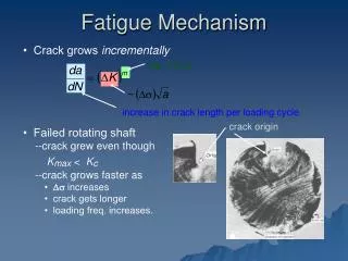
Mechanism
Mechanism. Bilingual Section Ies Pedro de Valdivia Author : Juan Carlos Parejo Reja Voice and reviced by : Elisabeth Kate Orchard. Mechanism.

Mechanism
E N D
Presentation Transcript
Mechanism Bilingual Section Ies Pedro de Valdivia Author: Juan Carlos Parejo Reja Voice and reviced by: Elisabeth Kate Orchard
Mechanism • A lever is a simple machine that makes work easier for use; it involves moving a load around a pivot using a force. In a lever there is a load, a pivot and an Effort (force).Levers are amongst the oldest form of mechanical system.
Levers • The input of this system is called the effort and the output is called the load. In the image, we have the input as F1 and the output as F2. The bar pivots on a fixed point (fulcrum).
Levers • The principle of the lever tells us that the lever is in static equilibrium, with all forces balancing, if F1D1 = F2D2. • In order to lift a bigger load (L1) the distance to the fulcrum has to increase (D2) or the distance D1 has to decrease.
First Class Lever • First Class Lever • With this type of lever the fulcrum is situated between the load and the applied force
Second Class Lever • Second Class Lever • With this type of lever the load is situated between the fulcrum and the applied force.
Third Class Lever • Third Class Lever • With this type of lever the force is applied between the load and the fulcrum.
Exercices • 1º You need to lift a load of 200 kg (F1). The distance from the load to the pivot(D1) is 6 meters and the distance from the pivot to • where the force is applied (D2) is 20 meters. Calculate the value of F1.
Exercices • 2º On the lever showed in the image D1 = 20, D2 = 400 and F1 = 300 Kg. Calculate the value of F2 • 3º On the same image, calculate the value of D1 if D2 = 70m, F1 = 300Kg and F2 = 60kg
Exercices • Write the lever class of every object
Pulley • A pulley is a wheel with a groove along its edge, for holding a rope or cable.
Pulleys • Pulleys are usually used to reduce the amount of force needed to lift a load. However, the same amount of work is necessary for the load to reach the same height as would be necessary without the pulleys. The magnitude of the force is reduced, but it must act over a longer distance
Types of pulleys • 1º Fixed: A fixed pulley has a fixed axle. That is, the axle is ""fixed"" or anchored in a place ( maybe the roof, ..). A fixed pulley is used to redirect the force in a rope A fixed pulley has a mechanical advantage of 1 • 1.mechanical advantage (MA) is the factor by which a mechanism multiplies the force put into it
Types of pulleys • 2º Movable: A movable pulley has a free axle. That is, the axle is "free" to move in space. A movable pulley is used to transform forces. A movable pulley has a mechanical advantage of 2.
Types of pulleys • 3º Compound A compound pulley is a combination of fixed and movable pulley systems.The simplest theory of operation for a pulley system assumes that the pulleys and ropes are weightless, and that there is no energy loss due to friction. It is also assumed that the ropes do not stretch.
compound pulley • 1º A basic equation for a pulley: In equilibrium, the force F on the pulley axle is equal and opposite to the sum of the tensions in each line leaving the pulley, and these tensions are equal.
compound pulley • Example 2 - A simple pulley system - a single movable pulley lifting a unit weight. The tension in each line is half the unit weight and an advantage of 2.
compound pulley • Example 3 - Another simple pulley system similar to example 2, but in which the lifting force is redirected downward.
compound pulley • A practical compound pulleyExercices: • Calculate the advantage of this pulley system
compound pulley • Example 4 - A simple compound pulley system - a movable pulley and a fixed pulley lifting a unit weight. The tension in each line is one third the unit weight
compound pulley • Example 5 - a movable pulley and a fixed pulley lifting a unit weight, with an additional pulley redirecting the lifting force downward. The tension in each line is one third the unit weight. • Which is its M.A?
compound pulley • Example 6 - A more complicated compound pulley system. The tension in each line is one quarter of the unit weight. It has an advantage of 4.
Gear • Gears or toothed wheels are type drives which are used to transmit motion between two shafts or a shaft and a component having linear motion, by meshing of two or more gears.
Gear • The ratio of the rotational speeds of two meshed gears is called the Gear ratio.
Worm Gear • If you want to create a high gear ratio, nothing beats the worm gear. In a worm gear, a threaded shaft engages the teeth on a gear. Each time the shaft spins one revolution, the gear moves one tooth forward. If the gear has 60 teeth, you have a 60:1 gear ratio in a very small package. Here is one example
Gear Exercices. What is the output in revolutions per minute at Gear C?
Gear Exercices. Gear A revolves at 90revs/min. What is the output and direction at Gear C.
Gear Exercices. Calculate the output speed (the speed at which the blue gear move) if: V1= 3000 (Orange gear) and t1=20 teeth T2 = 50 teeth T3 = 200 teeth
Compounds Gears In a compound gear, all gears are fixed on the same axel moving at the same speed. This is an example of a “compound gear train”. Gear A rotates in a clockwise direction at 30 revs/min. What is the output in revs/min at D and what is the direction of rotation ?
Gear and belt The advantages of chains and belts are light weight, the ability to separate the two gears by some distance, and the ability to connect many gears together on the same chain or belt
Gear and belt In this image, you can see some toothed belt to connect the axil motor to other componets of the car engine
Pulley systems The diagram shows a small driver pulley ( on the left) pulling round a larger driven pulley. The rpm (revolutions per minute) of the larger driven pulley wheel will be less than the smaller driver pulley wheel.
Pulley systems Pulley systems are used when there is a need to transmit rotary motion.. It is a simple mechanical device to winch up and down a rope. When the motor is turned on it revolves the driver pulley wheel. The belt causes the driven pulley wheel to rotate as well, winding out the rope.
Gear wheels and chains Everyone has used a bicycle and noticed that it is driven by a large driver gear wheel (pedal gear) with pedals attached. Smaller gears at the back are driven round, in turn driving round the back wheel. As the back wheel turns the bicycle moves forwards. Gears driven by chains are used in motorcycles, in car engines , etc.
Rack and pinion The rack and pinion gear system allows rotary motion of the steering wheel to be converted to linear motion.
Rack and pinion The diagram shows a vehicle and its steering system. This allows the steering wheel to turn the wheels left and right so that it can be steered.
Crank-connecting rod • A Crank-connecting-rod is a Mechanism for transformation of rectilineal motion in rotatory one and vice versa.
Crankshaft The crankshaft( in red), sometimes casually abbreviated to crank, is the part of an engine which translates reciprocating linear piston motion into rotation. See more about the engine here
Cam and follower system A cam and follower system is a mechanism that uses a cam ( blue piece) and follower to create a specific motion. The cam is in most cases merely a flat piece of metal that has a specific shape.