SIMPLE PHASE LOCKED LOOP
SIMPLE PHASE LOCKED LOOP. PRESENTED BY :- Vivek Pathak (1409904) Abhishek Solanki (1409905) Varad Kinjal Pooja. What is PLL?. PLL = Phase Lock Loop


SIMPLE PHASE LOCKED LOOP
E N D
Presentation Transcript
SIMPLE PHASE LOCKED LOOP PRESENTED BY:- Vivek Pathak (1409904) AbhishekSolanki (1409905) Varad Kinjal Pooja
What is PLL? • PLL = Phase Lock Loop • A circuit which synchronizes an adjustable oscillator with another oscillator by the comparison of phase between the two signals. • An electronic circuit that synchronizes itself to an external reference signal.
What is it for? • To generate High Frequency Clock in Microprocessor. • In Mobile Communication to generate Carrier Frequency. • Can you think of any other Application? Actually there are many.
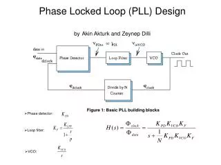
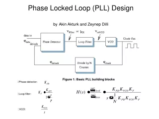
Parts of a PLL • Phase Detector • Filter • Voltage Controlled Oscillator
Parts of a PLL • Phase Detector • Acts as comparator • Produces a voltage proportional to the phase difference between input and output signal • Voltage becomes a control signal
Implementation of PD • Phase Detector is an XOR gate.
Parts of a PLL • Filter • Determines dynamic characteristics of PLL • Specify Capture Range (bandwidth) • Specify Tracking Range • Receives signal from Phase Detector and filters accordingly
Parts of a PLL • Voltage Controlled Oscillator • Set tuning range • Set noise margin • Creates low noise clock oscillation Wout = Wo+Kvco Vcont
Locked Condition • Locked Condition d/dt(φin-φout)=0 This implies that win = wout
Vi and Vout has at the same frequency W1 • The phase detector must produce V1 • Hence, VCO is dynamically changing and PD is creating VControl to adjust for the phase difference. • The PLL is in the Locked state
Application of PLL • Frequency Multiplications The feedback loop has frequency division. Frequency division is implemented using a counter.
Jitter Reduction • Clock Skew Reduction Buffers are used to distribute the clock Embed the buffer within the loop
Other applications include: • Demodulation of both FM and AM signals • Recovery of small signals that otherwise would be lost in noise (lock-in amplifier) • Recovery of clock timing information from a data stream such as from a disk drive • Clock multipliers in microprocessors that allow internal processor elements to run faster than external connections, while maintaining precise timing relationships • DTMF decoders, modems, and other tone decoders, for remote control and telecommunications