Download
1 / 51
560 likes | 934 Views
Behavioral Design Style Registers, Counters, Shift Registers. Resources. Sundar Rajan, Essential VHDL: RTL Synthesis Done Right Chapter 4, Registers and Latches Chapter 5, Counters and Simple Arithmetic Functions. Behavioral Design Style.

E N D
Behavioral Design StyleRegisters, Counters, Shift Registers ECE 545 – Introduction to VHDL
Resources • Sundar Rajan, Essential VHDL: RTL Synthesis • Done Right • Chapter 4, Registers and Latches • Chapter 5, Counters and Simple • Arithmetic Functions ECE 545 – Introduction to VHDL
Behavioral Design Style ECE 545 – Introduction to VHDL
Behavioral VHDL (subset) Major instructions Sequential statements General • process statement (process) • sequential signal assignment () Registers, counters, shift registers, etc. • if-then-else statement State machines • case-when statement Testbenches • loops (for-loop, while-loop) ECE 545 – Introduction to VHDL
Anatomy of a Process OPTIONAL [label:] process[(sensitivity list)] [declaration part] begin statement part end process; ECE 545 – Introduction to VHDL
What is a PROCESS? • A process is a sequence of instructions referred to as sequential statements. The Keyword PROCESS • A process can be given a unique name using an optional LABEL • This is followed by the keyword PROCESS • The keyword BEGIN is used to indicate the start of the process • All statements within the process are executed SEQUENTIALLY. Hence, order of statements is important. • A process must end with the keywords END PROCESS. TESTING: process begin TEST_VECTOR<=“00”; wait for 10 ns; TEST_VECTOR<=“01”; wait for 10 ns; TEST_VECTOR<=“10”; wait for 10 ns; TEST_VECTOR<=“11”; wait for 10 ns; end process; ECE 545 – Introduction to VHDL
List of signals to which the process is sensitive. Whenever there is an event on any of the signals in the sensitivity list, the process fires. Every time the process fires, it will run in its entirety. WAIT statements are NOT ALLOWED in a processes with SENSITIVITY LIST. label: process (sensitivity list) declaration part begin statement part end process; PROCESS with a SENSITIVITY LIST ECE 545 – Introduction to VHDL
Processes in VHDL • Processes Describe Sequential Behavior • Processes in VHDL Are Very Powerful Statements • Allow to define an arbitrary behavior that may be difficult to represent by a real circuit • Not every process can be synthesized • Use Processes with Caution in the Code to Be Synthesized • Use Processes Freely in Testbenches ECE 545 – Introduction to VHDL
Use of Processes in the Synthesizable Code ECE 545 – Introduction to VHDL
All signals which appear on the left of signal assignment statement (<=) are outputs e.g. y, z All signals which appear on the right of signal assignment statement (<=) or in logic expressions are inputse.g. w, a, b, c All signals which appear in the sensitivity list are inputs e.g. clk Note that not all inputs need to be included in the sensitivity list Component Equivalent of a Process clk y w priority a z b c priority: PROCESS (clk) BEGIN IF w(3) = '1' THEN y <= "11" ; ELSIF w(2) = '1' THEN y <= "10" ; ELSIF w(1) = c THEN y <= a and b; ELSE z <= "00" ; END IF ; END PROCESS ; ECE 545 – Introduction to VHDL
Registers ECE 545 – Introduction to VHDL
Q D Clock D latch Truth table Graphical symbol Q(t+1) Clock D Q(t) – 0 0 1 0 1 1 1 Timing diagram t t t t 1 2 3 4 Clock D Q Time ECE 545 – Introduction to VHDL
Q D Clock D flip-flop Truth table Graphical symbol Q(t+1) Clk D 0 0 1 1 – Q(t) 0 Q(t) 1 – Timing diagram t t t t 1 2 3 4 Clock D Q Time ECE 545 – Introduction to VHDL
Q D Clock D latch LIBRARY ieee ; USE ieee.std_logic_1164.all ; ENTITY latch IS PORT ( D, Clock : IN STD_LOGIC ; Q : OUT STD_LOGIC) ; END latch ; ARCHITECTURE Behavior OF latch IS BEGIN PROCESS ( D, Clock ) BEGIN IF Clock = '1' THEN Q <= D ; END IF ; END PROCESS ; END Behavior; ECE 545 – Introduction to VHDL
D flip-flop LIBRARY ieee ; USE ieee.std_logic_1164.all ; ENTITY flipflop IS PORT ( D, Clock : IN STD_LOGIC ; Q : OUT STD_LOGIC) ; END flipflop ; ARCHITECTURE Behavior_1 OF flipflop IS BEGIN PROCESS ( Clock ) BEGIN IF Clock'EVENT AND Clock = '1' THEN Q <= D ; END IF ; END PROCESS ; END Behavior_1 ; Q D Clock ECE 545 – Introduction to VHDL
D flip-flop LIBRARY ieee ; USE ieee.std_logic_1164.all ; ENTITY flipflop IS PORT ( D, Clock : IN STD_LOGIC ; Q : OUT STD_LOGIC) ; END flipflop ; ARCHITECTURE Behavior_2 OF flipflop IS BEGIN PROCESS BEGIN WAIT UNTIL Clock'EVENT AND Clock = '1' ; Q <= D ; END PROCESS ; END Behavior_2 ; Q D Clock ECE 545 – Introduction to VHDL
D flip-flop with asynchronous reset LIBRARY ieee ; USE ieee.std_logic_1164.all ; ENTITY flipflop IS PORT ( D, Resetn, Clock : IN STD_LOGIC ; Q : OUT STD_LOGIC) ; END flipflop ; ARCHITECTURE Behavior OF flipflop IS BEGIN PROCESS ( Resetn, Clock ) BEGIN IF Resetn = '0' THEN Q <= '0' ; ELSIF Clock'EVENT AND Clock = '1' THEN Q <= D ; END IF ; END PROCESS ; END Behavior ; Q D Clock Resetn ECE 545 – Introduction to VHDL
D flip-flop with synchronous reset LIBRARY ieee ; USE ieee.std_logic_1164.all ; ENTITY flipflop IS PORT ( D, Resetn, Clock : IN STD_LOGIC ; Q : OUT STD_LOGIC) ; END flipflop ; ARCHITECTURE Behavior OF flipflop IS BEGIN PROCESS BEGIN WAIT UNTIL Clock'EVENT AND Clock = '1' ; IF Resetn = '0' THEN Q <= '0' ; ELSE Q <= D ; END IF ; END PROCESS ; END Behavior ; Q D Clock Resetn ECE 545 – Introduction to VHDL
8 8 Resetn D Q Clock reg8 8-bit register with asynchronous reset LIBRARY ieee ; USE ieee.std_logic_1164.all ; ENTITY reg8 IS PORT ( D : IN STD_LOGIC_VECTOR(7 DOWNTO 0) ; Resetn, Clock : IN STD_LOGIC ; Q : OUT STD_LOGIC_VECTOR(7 DOWNTO 0) ) ; END reg8 ; ARCHITECTURE Behavior OF reg8 IS BEGIN PROCESS ( Resetn, Clock ) BEGIN IF Resetn = '0' THEN Q <= "00000000" ; ELSIF Clock'EVENT AND Clock = '1' THEN Q <= D ; END IF ; END PROCESS ; END Behavior ;` ECE 545 – Introduction to VHDL
N N Resetn D Q Clock regn N-bit register with asynchronous reset LIBRARY ieee ; USE ieee.std_logic_1164.all ; ENTITY regn IS GENERIC ( N : INTEGER := 16 ) ; PORT ( D : IN STD_LOGIC_VECTOR(N-1 DOWNTO 0) ; Resetn, Clock : IN STD_LOGIC ; Q : OUT STD_LOGIC_VECTOR(N-1 DOWNTO 0) ) ; END regn ; ARCHITECTURE Behavior OF regn IS BEGIN PROCESS ( Resetn, Clock ) BEGIN IF Resetn = '0' THEN Q <= (OTHERS => '0') ; ELSIF Clock'EVENT AND Clock = '1' THEN Q <= D ; END IF ; END PROCESS ; END Behavior ; ECE 545 – Introduction to VHDL
N N N-bit register with enable LIBRARY ieee ; USE ieee.std_logic_1164.all ; ENTITY regn IS GENERIC ( N : INTEGER := 8 ) ; PORT ( D : IN STD_LOGIC_VECTOR(N-1 DOWNTO 0) ; Enable, Clock : IN STD_LOGIC ; Q : OUT STD_LOGIC_VECTOR(N-1 DOWNTO 0) ) ; END regn ; ARCHITECTURE Behavior OF regn IS BEGIN PROCESS (Clock) BEGIN IF (Clock'EVENT AND Clock = '1' ) THEN IF Enable = '1' THEN Q <= D ; END IF ; END IF; END PROCESS ; END Behavior ; Enable Q D Clock regn ECE 545 – Introduction to VHDL
Counters ECE 545 – Introduction to VHDL
2 Clear Q upcount Clock 2-bit up-counter with synchronous reset LIBRARY ieee ; USE ieee.std_logic_1164.all ; USE ieee.std_logic_unsigned.all ; ENTITY upcount IS PORT ( Clear, Clock : IN STD_LOGIC ; Q : BUFFER STD_LOGIC_VECTOR(1 DOWNTO 0) ) ; END upcount ; ARCHITECTURE Behavior OF upcount IS BEGIN upcount: PROCESS ( Clock ) BEGIN IF (Clock'EVENT AND Clock = '1') THEN IF Clear = '1' THEN Q <= "00" ; ELSE Q <= Q + “01” ; END IF ; END IF; END PROCESS; END Behavior ; ECE 545 – Introduction to VHDL
Enable 4 Q Clock upcount Resetn 4-bit up-counter with asynchronous reset (1) LIBRARY ieee ; USE ieee.std_logic_1164.all ; USE ieee.std_logic_unsigned.all ; ENTITY upcount IS PORT ( Clock, Resetn, Enable : IN STD_LOGIC ; Q : OUT STD_LOGIC_VECTOR (3 DOWNTO 0)) ; END upcount ; ECE 545 – Introduction to VHDL
Enable 4 Q Clock upcount Resetn 4-bit up-counter with asynchronous reset (2) ARCHITECTURE Behavior OF upcount IS SIGNAL Count : STD_LOGIC_VECTOR (3 DOWNTO 0) ; BEGIN PROCESS ( Clock, Resetn ) BEGIN IF Resetn = '0' THEN Count <= "0000" ; ELSIF (Clock'EVENT AND Clock = '1') THEN IF Enable = '1' THEN Count <= Count + 1 ; END IF ; END IF ; END PROCESS ; Q <= Count ; END Behavior ; ECE 545 – Introduction to VHDL
Shift Registers ECE 545 – Introduction to VHDL
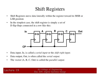
Shift register D D D D Q Q Q Q Q(1) Q(0) Q(2) Q(3) Sin Clock Enable ECE 545 – Introduction to VHDL
Shift Register With Parallel Load D(0) D D D D Q Q Q Q Load D(3) D(1) D(2) Sin Clock Enable Q(3) Q(2) Q(1) Q(0) ECE 545 – Introduction to VHDL
4 4 Enable D Q Load Sin shift4 Clock 4-bit shift register with parallel load (1) LIBRARY ieee ; USE ieee.std_logic_1164.all ; ENTITY shift4 IS PORT ( D : IN STD_LOGIC_VECTOR(3 DOWNTO 0) ; Enable : IN STD_LOGIC ; Load : IN STD_LOGIC ; Sin : IN STD_LOGIC ; Clock : IN STD_LOGIC ; Q : BUFFER STD_LOGIC_VECTOR(3 DOWNTO 0) ) ; END shift4 ; ECE 545 – Introduction to VHDL
4 4 Enable D Q Load Sin shift4 Clock 4-bit shift register with parallel load (2) ARCHITECTURE Behavior_1 OF shift4 IS BEGIN PROCESS (Clock) BEGIN IF Clock'EVENT AND Clock = '1' THEN IF Load = '1' THEN Q <= D ; ELSIF Enable = ‘1’ THEN Q(0) <= Q(1) ; Q(1) <= Q(2); Q(2) <= Q(3) ; Q(3) <= Sin; END IF ; END IF ; END PROCESS ; END Behavior_1 ; ECE 545 – Introduction to VHDL
4 4 Enable D Q Load Sin shift4 Clock 4-bit shift register with parallel load (3) ARCHITECTURE Behavior_2 OF shift4 IS BEGIN PROCESS BEGIN WAIT UNTIL Clock'EVENT AND Clock = '1' ; IF Load = '1' THEN Q <= D ; ELSIF Enable = ‘1’ THEN Q(3) <= Sin; Q(2) <= Q(3) ; Q(1) <= Q(2); Q(0) <= Q(1) ; END IF ; END PROCESS ; END Behavior_2 ; Incorrect!!! ECE 545 – Introduction to VHDL
Enable N N D Q Load Sin shiftn Clock N-bit shift register with parallel load (1) LIBRARY ieee ; USE ieee.std_logic_1164.all ; ENTITY shiftn IS GENERIC ( N : INTEGER := 8 ) ; PORT ( D : IN STD_LOGIC_VECTOR(N-1 DOWNTO 0) ; Enable : IN STD_LOGIC ; Load : IN STD_LOGIC ; Sin : IN STD_LOGIC ; Clock : IN STD_LOGIC ; Q : BUFFER STD_LOGIC_VECTOR(N-1 DOWNTO 0) ) ; END shiftn ; ECE 545 – Introduction to VHDL
Enable N N D Q Load Sin shiftn Clock N-bit shift register with parallel load (2) ARCHITECTURE Behavior OF shiftn IS BEGIN PROCESS (Clock) BEGIN IF (Clock'EVENT AND Clock = '1' ) THEN IF Load = '1' THEN Q <= D ; ELSIF Enable = ‘1’ THEN Genbits: FOR i IN 0 TO N-2 LOOP Q(i) <= Q(i+1) ; END LOOP ; Q(N-1) <= Sin ; END IF; END IF ; END PROCESS ; END Behavior ; ECE 545 – Introduction to VHDL
Sequential Statements ECE 545 – Introduction to VHDL
Anatomy of a Process [label:] process[(sensitivity list)] [declaration part] begin statement part end process; ECE 545 – Introduction to VHDL
Statement Part • Contains Sequential Statements to be Executed Each Time the Process Is Activated • Analogous to Conventional Programming Languages ECE 545 – Introduction to VHDL
Sequential Statements (1) • If Statement • else and elsif are optional ifboolean expression then statements elsif boolean expression then statements else boolean expression then statements end if; ECE 545 – Introduction to VHDL
If Statement - Example SELECTOR: process begin WAIT UNTIL Clock'EVENT AND Clock = '1' ; IF Sel = “00” THEN f <= x1; ELSIF Sel = “10” THEN f <= x2; ELSE f <= x3; END IF; end process; ECE 545 – Introduction to VHDL
Sequential Statements (2) [case label:] casecondition is when choice_1 => statements when choice_2 => statements when choice_n => statements end case; • Case Statement • Choices Have to Cover All Possible Values of the Condition • Use others to specify all remaining cases ECE 545 – Introduction to VHDL
Case Statement - Example FSM_transitions: PROCESS ( Resetn, Clock ) BEGIN IF Resetn = '0' THEN y <= S1 ; ELSIF (Clock'EVENT AND Clock = '1') THEN CASE y IS WHEN S1 => IF s = '0' THEN y <= S1; ELSE y <= S2 ; END IF ; WHEN S2 => IF z = '0' THEN y <= S2 ; ELSE y <= S3 ; END IF ; WHEN S3 => IF s = '1' THEN y <= S3 ; ELSE y <= S1 ; END IF ; END CASE ; END IF ; END PROCESS ; ECE 545 – Introduction to VHDL
Sequential Statements (3) • For-Loop Statement • Repeats a Section of VHDL Code • Example: process every element in an array in the same way [loop label:] foridentifier in discrete_range loop { sequential statement } end loop [loop label]; ECE 545 – Introduction to VHDL
For-Loop Statement - Example TEST_DATA_GENERATOR: process begin TEST_AB<="00"; TEST_SEL<="00"; for I in 0 to 3 loop for J in 0 to 3 loop wait for 10 ns; TEST_AB<=TEST_AB+"01"; end loop; TEST_SEL<=TEST_SEL+"01"; end loop; end process; ECE 545 – Introduction to VHDL
Sequential Statements (4) • While-Loop Statement • Repeats a Section of VHDL Code • Example: process every element in an array in the same way [loop label:] whileboolean_expression loop { sequential statement } end loop [loop label]; ECE 545 – Introduction to VHDL
While-Loop Statement - Example TEST_DATA_GENERATOR: process begin TEST_AB<="000"; TEST_SEL<="000"; while TEST_SEL /= “100” while TEST_AB /= “100” loop wait for 10 ns; TEST_AB<=TEST_AB+“001"; end loop; TEST_SEL<=TEST_SEL+“001"; TEST_AB <= “000”; end loop; end process; ECE 545 – Introduction to VHDL
Next Statement (1) • Next Statement • Can appear only inside of a loop • Used to terminate the current iteration of a loop when CONDITION is TRUE; • When the current iteration is terminated, the execution begins with the next iteration value next [loop_label] [when CONDITION ]; ECE 545 – Introduction to VHDL
Next Statement (2) • Next Statement • If the loop_label is present, the current iteration of the loop with a given label is terminated • If the loop_label is absent, the innermost loop is terminated • If the CONDITION is omitted, the appropriate loop iteration is always terminated next [loop label] [when CONDITION ]; ECE 545 – Introduction to VHDL
Next Statement - Example TEST_DATA_GENERATOR: process begin TEST_A<=“11"; for I in 0 to 3 loop TEST_A<=TEST_A+“01"; TEST_B <= “11”; for J in 0 to 3 loop TEST_B<=TEST_B+”01"; next when I=J; next outer when I=1; wait for 10 ns; end loop; end loop; end process; ECE 545 – Introduction to VHDL
Exit Statement • Exit Statement • Behaves in the same way as the next statement except that the entire loop statement is terminated exit [loop_label] [when CONDITION ]; ECE 545 – Introduction to VHDL
Exit Statement - Example TEST_DATA_GENERATOR: process begin TEST_A<=“11"; for I in 0 to 3 loop TEST_A<=TEST_A+“01"; TEST_B <= “11”; for J in 0 to 3 loop TEST_B<=TEST_B+”01"; exit when I=J; exit outer when I>2; wait for 10 ns; end loop; end loop; end process; ECE 545 – Introduction to VHDL
Mixing Design Styles Inside of an Architecture ECE 545 – Introduction to VHDL