Download
1 / 17
170 likes | 196 Views
Proposal for path loss model development for TGad channel models in 60 GHz band, emphasizing complexities and interrelations between path loss and impulse response. Includes path loss values derivation and modeling using directional antennas with beamforming algorithm.

E N D
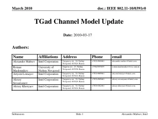
Path Loss Model Development for TGad Channel Models Date: 2009-05-11 Authors: Alexander Maltsev, Intel Corp.
Abstract This contribution proposes an approach for path loss model development for TGad channel models Alexander Maltsev, Intel Corp.
Development of Path Loss Model • The conference room channel model proposed in [1] provides complex amplitudes of different rays taking into account the attenuation of the signal between the transmitter and receiver in a real scale. So each ray has some information about the propagation loss of the channel and some information about the impulse response. • This is different from the traditional channel modeling approach where separate models are generated for the path loss and the channel impulse response. • The reason for using different approach is a difference in propagation channel characteristics between the 60 GHz band and the traditional WLAN bands (2.4 GHz and 5 GHz). • In the 2.4 GHz and 5 GHz bands many channel rays contribute to the total received signal power even if multiple antennas are used and spatial signal processing algorithms are applied. Thus the separation between path loss and impulse response models is possible. Alexander Maltsev, Intel Corp.
Development of Path Loss Model (Cont’d) • In the 60 GHz band the path loss and channel impulse models are more complexly interrelated. • For example, many beamforming algorithms using directional antennas are filtering out (in a spatial domain) a single cluster of the propagation channel. So both the frequency selectivity and propagation loss of the channel will be only defined by characteristics of a single cluster. Thus for the same TX and RX locations, the propagation loss and channel impulse response may be significantly different depending on the characteristics of the cluster used for communications and also directivity properties of antennas and used beamforming algorithm. • The developed conference room channel model may be directly applicable for link level simulations where an independent path loss model is not required. • However, the path loss model is important for network (or MAC) simulations where direct application of the conference room channel model and direct modeling of the beamforming algorithms may unnecessary complicate the network simulations. Alexander Maltsev, Intel Corp.
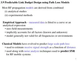
Development of Path Loss Model (Cont’d) • It is possible to derive an independent path loss model if some assumptions about the 60 GHz WLAN system such as antenna type and beamforming algorithm are fixed. • In this contribution the path loss model was developed using the basic steerable directional antenna model from [1] with beamwidths from 600 to 100 and the beamforming algorithm adjusting TX and RX antennas along the ray with maximum power. • The path loss values were obtained for many snapshots of the conference room channel model. Then the path loss model was derived. [1] IEEE doc. 802.11-09/0334r0 “Channel Models for 60 GHz WLAN Systems ” Alexander Maltsev, Intel Corp.
Average Path Loss vs. Distance for LOS Scenario • Average path loss vs. distance curve is plotted for 300 antenna beamwidth • It was verified that curves for other antenna beamwidths in the range from 600 to 100 match each other very closely (within 0.1 dB). • The curve may be well approximated by the r2 law. Alexander Maltsev, Intel Corp.
Histograms of Path Loss Realizations for LOS Scenario • It may be seen that for LOS scenario deviations of actual path loss values are very low (because the most part of the channel power is the LOS ray) • No shadow fading may be assumed for LOS scenario. All LOS realizations of the channel with the same distance will have the same path loss. Alexander Maltsev, Intel Corp.
Path Loss Model for LOS Scenario • Based on the obtained simulation results a simple path loss model may be proposed for LOS scenario based on Friis transmission equation: • Where ALOS = 32.5 dB, nLOS = 2.0, f is the carrier frequency in GHz, R is the distance between TX and RX in m. • The value of A is specific for the selected type of antenna and beamforming algorithm. • ALOS depends on the antenna beamwidth, but for the considered beamwidth range from 600 to 100 the variation will be very small (< 0.1 dB) • There is no shadowing for the LOS scenario. Alexander Maltsev, Intel Corp.
Simulated Average Path Loss and Path Loss Predicted Using Model for LOS Scenario • The plot shows path loss curves obtained from the statistical conference room channel model, path loss model and several experimental points • It may be seen that the path loss model is well matched to both the statistical channel model and experimental data Alexander Maltsev, Intel Corp.
Path Loss Model Development for NLOS Scenario • The similar assumptions and procedure as for the LOS scenario were used for the developed of the path loss model for the NLOS scenario of the conference room channel model. • The basic steerable directional antenna model with beamwidths from 600 to 100 and the beamforming algorithm adjusting TX and RX antennas along the ray with maximum power were used. Alexander Maltsev, Intel Corp.
Average Path Loss vs. Distance for NLOS Scenario • Average path loss vs. distance curves are plotted for antenna beamwidths from 600 to 100. • The curves for different beamwidths are close to each other (within 1 dB) • All curves have the same shape and may be approximated by the r0.6 law. Alexander Maltsev, Intel Corp.
Histograms of Path Loss Realizations for NLOS Scenario • It may be seen that for the NLOS scenario the dispersion of the path loss is significant and shadow fading model should be introduced. • Normal (Gaussian) in dB (log-normal in absolute scale) distribution may be used in the shadow fading model because it provides close matching of the distribution obtained from the simulations. Alexander Maltsev, Intel Corp.
Standard Deviation of Shadow Fading Model for NLOS Scenario as Function of Distance • The standard deviation of the path loss depends on the TX – RX separation but approximately may be taken equal to 3.3dB as it follows from the left plot. • The dependence of on antenna beamwidth is very small because for the considered range of antenna beamwidths (600 to 100) antenna selects only one spatial cluster for most of the cases Alexander Maltsev, Intel Corp.
Path Loss Model for NLOS Scenario • Based on the obtained results an average path loss model may be proposed for NLOS scenario as: • Where ANLOS = 51.5 dB, nNLOS = 0.6, f is the carrier frequency in GHz, R is the distance between TX and RX in m. • The values of ANLOS and nNLOS are specific for the selected type of antenna and beamforming algorithm. • ANLOS depends on the antenna beamwidth, but for the considered beamwidth range from 600 to 100 the variation will be very small (< 1 dB) • Additionally, the shadow fading (SF) model should be applied. The SF values distribution is normal in dB (log-normal in absolute values) with standard deviation = 3.3 dB. Alexander Maltsev, Intel Corp.
Simulated Average Path Loss and Path Loss Predicted Using Model for NLOS Scenario • The plot shows path loss curves obtained from the statistical conference room channel model, path loss model and several experimental points. • It may be seen that the path loss model is well matched to both the statistical channel model and experimental data Alexander Maltsev, Intel Corp.
Path Loss Model Summary • If antenna system parameters and beamforming algorithms are fixed then it is possible to derive an average path loss model using the standard form: • Where A and n are parameters specific for the scenario and antenna system, f is the carrier frequency in GHz, R is the distance between TX and RX in m. • The normal in dB SF model may be used together with the average path loss model. SF standard deviation is specific for the scenario and antenna system parameters. • The path loss model parameters for the conference room scenario, basic steerable antenna model and maximum ray beamforming algorithm are: Alexander Maltsev, Intel Corp.
Conclusion • It is more difficult to decouple path loss and channel impulse response for the 60 GHz WLAN channel modeling than for 2.4-5 GHz bands. • An independent path loss model may be derived if the type of antenna and beamforming algorithm are fixed. • The path loss model for the conference room environment was obtained for LOS and NLOS environments, for system with steerable antennas (with beamwidths from 100 to 600) and beamforming algorithm selecting the most powerful ray. • The proposed path loss model development approach may be used for the development of the path loss models for other TGad scenarios. • The developed path loss model is suitable for system performance evaluation and network simulations. Alexander Maltsev, Intel Corp.