Outdoor Path Loss Models for 802.11ah
100 likes | 484 Views
Outdoor Path Loss Models for 802.11ah. Authors:. Date: 2011-02-25. Slide 1. Summary. Following the discussion in [4] on channel models, we add here additional outdoor path loss models for Macro, Micro, Pico/Hotzone(Relay) deployments based on 3GPP LTE assumptions and COST231 channel models

Outdoor Path Loss Models for 802.11ah
E N D
Presentation Transcript
Outdoor Path Loss Models for 802.11ah Authors: Date: 2011-02-25 Ron Porat, Broadcom Slide 1
Summary • Following the discussion in [4] on channel models, we add here additional outdoor path loss models for Macro, Micro, Pico/Hotzone(Relay) deployments based on 3GPP LTE assumptions and COST231 channel models • It is anticipated that some of the scenarios proposed for 802.11ah fit better Hotzone deployments and some may fit better Macro deployments Ron Porat, Broadcom Slide 2
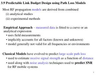
Recap - LTE Macro Path Loss Models • Macro cell propagation model for urban area is applicable for scenarios in urban and suburban areas outside the high rise core where the buildings are of nearly uniform height which is assumed to be 12m • h is the antenna height above roof top levels and assumed 15m (we plot path loss with 2m antenna as well) • R is in [km] and f in [MHz] • With LTE assumptions we get 15.3+37.6*log10(d) at 2GHz and where d is the distance in meters • Frequency dependency is seen in the term and contributes 7.3dB to the path loss difference between 2GHz and 900MHz. • In the following, we concentrate on path loss at 2GHz since most LTE models assume that frequency. Ron Porat, Broadcom Slide 3
LTE Micro-cell system simulation parameters (Table A.2.1.1-4 [1]) Ron Porat, Broadcom Slide 4
Other Path Loss Models • COST 231 - This path loss model for Macro and Micro deployments is used in the SCM channel model [3] • The Macro model is based on Hata model and assuming 2GHz frequency we get 35.2+35*log10(d) where d is the distance in meters • The Micro model is based on Walfish-Ikegami model and provides NLOS and LOS models. The NLOS path loss model for 2GHz is 35.7+38*log10(d). The LOS model for 2GHz is 35.7+26*log10(d) • 802.11n path loss model assumes one breakpoint with LOS propagation up to that point and an exponent 3.5 after • LTE-Advanced newer Pico path loss model [2] is 30.6+36.7*log10(d) Ron Porat, Broadcom Slide 5
Summary of Outdoor Path Loss Models at 2GHz • Note that Cost 231 Urban Macro, the new LTE-A Pico and LTE Macro with 2m antenna height exhibit similar path loss Ron Porat, Broadcom Slide 6
LTE-A Path Loss Models • LTE Rel.10 [2] (LTE-Advanced) added newer low power Hotzone deployment options and introduced newer path loss models that are partially based on measurements conducted by China Mobile [5][6] and include a NLOS formula and LOS formula. • Initially the two components were added together with a weight based on a probability function but later on changed to be treated separately. • For consistency [6], the Macro model was changed to include a LOS model and the NLOS model was adjusted • Hotzone Urban Model • PLLOS(d)=41.1+20.9log10(d) • PLNLOS(d)=32.9+37.5log10(d) • Prob(d)=0.5-min(0.5,5exp(-156/d))+min(0.5, 5exp(-d/30)) • Macro Urban Model • PLLOS(d)=30.8+24.2*log10(d) • PLNLOS(d)=2.7+42.8*log10(d) • Prob(d)=min(1,18/d)*(1-exp(-d/63))+exp(-d/63) Ron Porat, Broadcom Slide 7
LTE-A Hotzone Path Loss Models at 2GHz Ron Porat, Broadcom Slide 8
Conclusions • Several outdoor path loss models are shown with some variation. • We note that Cost231 Macro Urban, Cost231 Micro Urban, LTE Hotzone NLOS, LTE Pico and LTE Macro with antenna height 2m are very similar and models from this set can be chosen. • In addition, a link budget calculation or system simulation should include the following components: • Adjustment for different frequencies • Shadow fading with 10dB std • Penetration loss for indoor clients Ron Porat, Broadcom Slide 9
References [1] 3GPP TR 25.814 - Physical layer aspects for evolved Universal Terrestrial Radio Access (UTRA) – Annex A.2 system simulation scenario [2] 3GPP TR 36.814 - Further advancements for E-UTRA physical layer aspects, Annex A.2- system simulation scenario [3] 3GPP TR 25.996 - Technical Specification Group Radio Access Network; Spatial channel model for Multiple Input Multiple Output (MIMO) simulations [4] 11-11-0251-00-00ah-outdoor-channel_models-for-802-11ah.ppt [5] 3GPP TSG-RAN WG1 #56bis, R1-091566, China Mobile, Vodafone - Relay to UE channel model for LTE-Advanced [6] 3GPP TSG-RAN WG1 #58, R1-093270, China Mobile - Consideration on eNB-UE channel model Ron Porat, Broadcom Slide 10