Download
1 / 13
130 likes | 399 Views
Date: 2009-11-12. Path Loss Models for TGad Channel Models: Antenna and Dispersion Impact. Authors:. A brief overview of available Path-Loss models Impact of antenna diagram combined with dispersion of measurements for a given scenario

E N D
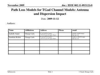
Date: 2009-11-12 Path Loss Models for TGad Channel Models: Antenna and Dispersion Impact Authors: I. Siaud, Orange Labs
A brief overview of available Path-Loss models Impact of antenna diagram combined with dispersion of measurements for a given scenario Antenna height impact: validity range and applications of the Earth-Plane model Outline I. Siaud, Orange Labs
A brief overview of path-loss models I. Siaud, Orange Labs
A brief overview of path-loss models at 60 GHz • The Friis transmission equation Free Space path-Loss model at any RF frequency carrier • One Slope Path-Loss Model (Coreira model [5]) • Motley-Keenan model Kwi : number of walls and floors of category i Lwi : penetration Loss per wall/floor of category material I. Siaud, Orange Labs
A brief overview of path-loss models • Modified Free Space path-loss model in multipath environment Updated in next sections of the document I. Siaud, Orange Labs
Why Considering this model? Selection of 2 predominant paths, mismatch antenna squint Additional sinusoidal spatial component depending on antenna height The Earth-Plane Model applied to 60 GHz Hypothesis : Phase difference Df between direct and reflected paths |Er|=> |r|=-1 I. Siaud, Orange Labs
Applications to 60 GHz and 5 GHz Similar antenna heights at Tx and Rx may involve local path loss attenuation Different antenna heights at Tx and Rx are more recommended in the case of limited energy ray capture and beamforming Larger antenna aperture at the receiver side in dynamic environment is more recommended (handled device) The Earth-Plane Model applied to 60 GHz I. Siaud, Orange Labs
In LOS, OLOS and NLOS, large dispersion of measurements in residential and Office environments for both sectoral and directive antennas Selection of measurements is done to generate accurate path-loss models Path-Loss models and antenna impact I. Siaud, Orange Labs
Large dispersion of measurements may involve in the case of directive antennas non realistic path-loss models A filtering of experimental points is required Path-Loss models and antenna impact I. Siaud, Orange Labs
Recommended path-Loss models by Orange Labs for residential Environments Path-Loss models and antenna impact I. Siaud, Orange Labs
Recommended Orange Labs models versus Earth-Plane Model Path-Loss models and antenna impact • Earth-Plane Model shall be used to model antenna pointing mismatch • Larger antenna aperture shall be preferred to reduce local path-loss attenuation resorting from restricted multipath combination I. Siaud, Orange Labs
Realistic path-Loss models require a accurate comparison between all available path-Loss models Antenna pointing mismatch may involve local attenuation that damage performance and link budget Earth-Plane path Loss model may be used to assess the impact of antenna height in the case of combination of 2 predominant paths and mismatch antenna alignment Path-Loss analysis show that directive antennas have to be considered in restrictive static case with Fixed devices and AP What are the appropriate models for link budget in the case of beamforming? Conclusion I. Siaud, Orange Labs
[1] IEEE doc. 802.11-09/0334r0 “Channel Models for 60 GHz WLAN Systems ” [2] A. Maltsev, E. Perahia, R. Maslennikov, A. Khoryaev, A. Sevastyanov, "Path-Loss Models for propagation channel models", IEEE doc. 802.11-09/0553r1, May 2009. [3] P. Pagani, N. Malhouroux, I. Siaud, "Characterization and modeling of the 60 GHz indoor channel in the office and residential environments, IEEE802.15.3c doc. n° 15-06-0041-00-3c, January 2006. [4] S.K.Yong, "TG3c Channel Model Final Report Presentation", IEEE 802.15-06-0483-02_003c, September 2007 [5] P.F.M. Smulders and L.M. Correia, “Characterization of Propagation in 60 GHz Radio Channels”,Electronics & Communication Engineering Journal, pp. 73–80, 1997. [6] H. Yang, P.F.M, Smulders, M.H.A.I Herben,. "Channel characteristics and transmission performance for various channel configurations at 60 GHz". EURASIP Journal of Wireless Communications and Networking, 2007(19613), 1-15. References I. Siaud, Orange Labs