Download
1 / 1
20 likes | 105 Views
This study explores the effectiveness of using embedded steel bars for shear strengthening of concrete beams, showcasing significant increases in load carrying capacity and deformational capacities. The results confirm the feasibility of this strengthening technique, offering enhanced ductility and resistance against detachment. The experimental program presented includes detailed configurations and test outcome analysis. The proposed strategy offers a solution to avoid shear failure in continuous slab strips and achieve higher levels of protection against fire and vandalism compared to other reinforcement techniques.

E N D
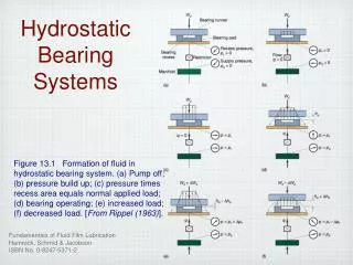
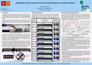
EMBEDMENT OF STEEL BARS FOR THE SHEAR STRENGTHENING OF CONCRETE ELEMENTS GLÁUCIADALFRÉ * Supervisors: Joaquim Barros * gmdalfre@civil.uminho.ptt Experimental Program The experimental program is formed by two series, A and B, composed of beams with a cross section of 150x300 mm2 and 300x300mm2, respectively, with a total length of 2450 mm and the shear strengthening/reinforcement configurations represented in Figure 3. • Resultsofthe experimental program • The applied loads versus deflection curves of the tested RC beams are presented in Figure 4. It can be noted that the use of embedded steel bars allowed significant increment of the shear resistance of reinforced concrete beams, regardless of the orientation of the bar. The effectiveness is not only in terms of the beam load carrying capacity, but also in terms of the ductility of the beam’s. Introduction An ongoing experimental program formed by continuous slab strips strengthened in flexure with NSM CFRP laminates is being carried out, and the obtained results show the possibility of increasing significantly the load carrying capacity of these elements, maintaining high levels of ductility. However, the occurrence of shear failure in the continuous slab strips limits the efficacy of the NSM technique. In general, the shear failure is followed by the detachment of the strengthened concrete cover layer (Figure 1). In the case of beams, NSM CFRP laminates can be applied into slits opened on the concrete cover of the lateral faces of the element. However, in case of slabs, the NSM shear strengthening has no applicability, and a strengthening strategy that avoids the occurrence of shear failure and provides extra resistance to the detachment of the NSM laminates is proposed in this work. According to the proposed strengthening strategy (Figure 2), holes are opened across the slab/beam thickness, with the desired inclinations, and bars are introduced into these holes and bonded to the concrete substrate with adhesive materials. To assess the effectiveness of this technique, a comprehensive experimental program was carried and the obtained results confirm the feasibility of the strengthening system. Figure 4: Relationship between the applied load versus the loaded section deflection The analysis of the results prompts the following remarks: (i) The ETS shear strengthening technique can convert a brittle shear failure in a ductile flexural failure. (ii) The maximum load and the deflection capacity of the beams reinforced with conventional stirrups were similar to the values registered on beams strengthened with ETS bars. Thus, it was verified the feasibility of using the ETS bars to correct construction/design deficiencies, strengthening or rehabilitation of structures that become unsafe due to changes in loading, use, configuration or seismic actions. (iii) The ETS shear strengthening elements have higher protection against fire and vandalism acts than FRP systems applied according to the Externally Bonded Reinforcing or Near Surface Mounted techniques. Conclusions According to the results it was verified the feasibility of using the proposed shear strengthening technique, since shear brittle failure mode can be avoided, resulting significant increases in load carrying and deformational capacities of the strengthened elements. Furthermore, appreciable levels of residual strength after the peak load were obtained. Acknowledgments The first author would like to acknowledge the National Council for Scientific and Technological Development (CNPq) – Brazil for financial support for scholarship (GDE 200953/2007-9). The research is part of PTDC/ECM/73099/2006 project supported by FCT. A Series B Series Figure 1: Slab strip failure mode Figure 2: Shear Strengthening concept Figure 3: Shear strengthening configurations