Hydrostatic Bearing Systems
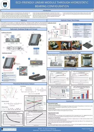
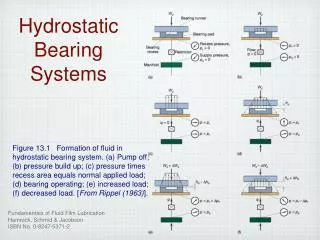
Hydrostatic Bearing Systems. Figure 13.1 Formation of fluid in hydrostatic bearing system. (a) Pump off; (b) pressure build up; (c) pressure times recess area equals normal applied load; (d) bearing operating; (e) increased load; (f) decreased load. [ From Rippel (1963) ].

Hydrostatic Bearing Systems
E N D
Presentation Transcript
Hydrostatic Bearing Systems Figure 13.1 Formation of fluid in hydrostatic bearing system. (a) Pump off; (b) pressure build up; (c) pressure times recess area equals normal applied load; (d) bearing operating; (e) increased load; (f) decreased load. [From Rippel (1963)].
Circular Step Pad & Pressure Figure 13.2 Radial-flow hydrostatic thrust bearing with circular step pad. Figure 13.3 Pressure distribution in radial-flow hydrostatic thrust bearing.
Pad Coefficients Load coefficient: Flow coefficient: Power coefficient: Figure 13.4 Chart for determining bearing pad coefficients for circular step thrust bearing. [From Rippel (1963)].
Annular Thrust Pad Bearing Figure 13.5 Configurations of annular thrust pad bearing. [From Rippel (1963)].
Pad Coefficients Load coefficient: Flow coefficient: Power coefficient: Figure 13.6 Chart for determining bearing pad coefficients for annular thrust pad bearings. [From Rippel (1963)].
Rectangular Hydrostatic Pad Figure 13.7 Rectangular hydrostatic pad.
Pad Coefficients Load coefficient: Flow coefficient: Power coefficient: Figure 13.8 Pad coefficients. (a) Square pad; (b) rectangular pad with B= 2L and b = l.
Compensated Hydrostatic Bearings Figure 13.9 Capillary-compensated hydrostatic bearing. [From Rippel (1963)]. Figure 13.10 Orifice-compensated hydrostatic bearing. [From Rippel (1963)].
Flow-Valve Compensation Figure 13.10 Constant-flow-valve compensation in hydrostatic bearing. [From Rippel (1963)].
Speed vs. Load Figure 14.1 Effect of speed on load for self-acting, gas-lubricated bearings. [From Ausman (1961).]
Rectangular-Step Thrust Bearing Figure 14.3 Transformation of rectangular slider bearing into circular sector bearing. Figure 14.2 Rectangular-step thrust bearing. [From Hamrock (1972).]
Optimum Step Parameters Figure 14.4 Effect of dimensionless bearing number on optimum step parameters. (a) For maximum dimensionless load-carrying capacity; (b) for maximum dimensionless stiffness. [From Hamrock (1972).]
Load-Carrying Capacity & Stiffness Figure 14.5 Effect of dimensionless bearing number on dimensionless load-carrying capacity and dimensionless stiffness. (a) For maximum dimensionless load-carrying capacity; (b) for maximum dimensionless stiffness. [From Hamrock (1972).]
Spiral-Groove Thrust Bearing Figure 14.6 Spiral-groove thrust bearing. [From Malanoski and Pan (1965).]
Spiral-Groove Thrust Bearing Characteristics Figure 14.7 Charts for determining characteristics of spiral-groove thrust bearings. (a) Groove factor; (b) load; (c) stiffness; (d) torque; (e) flow; (f) optimal groove geometry; (g) groove length factor. [From Reiger (1967).]
Pressure Perturbation Solution Figure 15.1 Design chart for radially loaded, self-acting, gas-lubricated journal bearings (isothermal first-order perturbation solution.) [From Ausman (1959).]
Pivoted-Pad Bearings Figure 15.3 Geometry of individual pivoted-pad bearing. [From Gunter et al. (1964)] Figure 15.4 Geometry of pivoted-pad journal bearing with three pads. [From Gunter et al. (1964)]
Herringbone-Groove Journal Bearing Figure 15.6 Configuration of concentric herringbone-groove journal bearing.
Parameters for Herringbone Bearing Figure 15.7 Charts for determining optimal herringbone-journal-bearing groove parameters for maximum radial load. Top plots are for grooved member rotating; bottom plots are for smooth member rotating. (a) Optimal film thickness ratio; (b) optimal groove width ratio. [From Hamrock and Fleming (1971)]
Parameters for Herringbone Bearing (cont.) Figure 15.7 Concluded. (c) Optimal groove length ratio; (d) optimal groove angle.
Load-Carrying Capacity Figure 15.8 Chart for determining maximum normal load-carrying capacity. (a) grooved member rotating; (b) smooth member rotating. [From Hamrock and Fleming (1971)]
Stability of Herringbone-Groove Bearings Figure 15.9 Chart for determining maximum stability of herringbone-groove bearings. [From Fleming and Hamrock (1974).]
Foil Bearing Figure 15.10 (a) Schematic illustration of a foil bearing; (b) free-body diagram of a section of foil.
Pressure in Foil Bearing Figure 15.11 Pressure distribution and film thickness in a foil bearing. [From Bhushan (2002).]
Lubrication of Rigid Cylinder Figure 16.1 Lubrication of a rigid cylinder near a plane. (a) Coordinates and surface velocities; (b) forces.
Cavitation Fingers Figure 16.2 Cavitation fingers.
Effect of Leakage Figure 16.3 Side-leakage effect on normal load component. Figure 16.4 Effect of leakage on tangential load component.
Contact Geometry Figure 16.5 Contact geometry. (a) Two rigid solids separated by a lubricant film: (a-1) y=0 plane; (a-2) x=0 plane. (b) Equivalent system of a rigid solid near a plane separated by a lubricant film: (b-1) y=0 plane; (b-2) x=0 plane. [From Brewe et al. (1979)].
Boundary Conditions & Nodal Structure Figure 16.6 Effect of boundary conditions. (a) Solution using full Sommerfeld boundary conditions; (b) solution using half Sommerfeld boundary condition; (c) solution using Reynolds boundary conditions. [From Brewe et al. (1970)]. Figure 16.7 Variable nodal structure used for numerical calculations. [From Brewe et al. (1979)].
Hydrodynamic Lift Figure 16.8 Effect of radius ratio on reduced hydrodynamic lift. [From Brewe et al. (1979)].
Comparison of Fully Flooded and Starved Contact Figure 16.11 Three-dimensional representation of pressure distributions for dimensionless minimum film thickness Hmin of 1.0 x 10⁻⁴. (a) Fully flooded condition; (b) starved condition. [From Brewe and Hamrock. (1982)].
Comparison of Fully Flooded and Starved Contact Figure 16.11 Three-dimensional representation of pressure distributions for dimensionless minimum film thickness Hmin of 1.0 x 10⁻³. (a) Fully flooded condition; (b) starved condition. [From Brewe and Hamrock. (1982)].
Pressure Contours - Starved Figure 16.13 Isobaric contour plots for three fluid inlet levels for dimensionless minimum film thickness Hmin of 1.0 x 10⁻⁴. (a) Fully flooded condition: dimensionless fluid inlet level Hin, 1.00; dimensionless pressure, where dP/dX=0, Pm, 1.20 x 10⁶; dimensionless load-speed ratio W/U, 1153.6. (b) Starved condition; Hin, 0.004; Pm = 1.19 x 10⁶; W/U = 862.6. (c) Starved condition: Hin =0.001; Pm = 1.13 x 10⁶; W/U = 567.8. [From Brewe and Hamrock. (1982)].
Inlet Level Effect Figure 16.14 Effect of fluid inlet level on film thickness reduction factor in flooded conjunctions. [From Brewe and Hamrock (1982)].
Lubricant Flow Figure 16.15 Lubricant flow for a rolling-sliding contact and corresponding pressure buildup. [From Ghosh et al. (1985)].
Pressure Distributions vs. Normal Velocity Parameter Figure 13.2 Radial-flow hydrostatic thrust bearing with circular step pad.
Performance Parameters Figure 16.19 Effect of radius ratio on dynamic load ratio. Dimensionless central film thickness Hmin, 1.0 x 10⁻⁴; dimensionless fluid inlet level Hin, 0.035. [From Ghosh et al. (1985)].
Peak Pressure vs. Radius Ratio Figure 16.20 Effect of radius ratio on dynamic peak pressure ratio. Dimensionless central film thickness Hmin, 1.0 x 10⁻⁴; dimensionless fluid inlet level Hin, 0.035. [From Ghosh et al. (1985)].
Contact Geometry Figure 17.1 Geometry of contacting elastic solids. [From Hamrock and Dowson (1981).]
Radii of Curvature Figure 17.2 Sign designations for radii of curvature of various machine elements. (a) Rolling elements; (b) ball bearing races; (c) rolling bearing races.
Pressure Distribution Pressure: Maximum pressure: Figure 17.3 Pressure distribution in ellipsoidal contact.
Ellipticity Parameter and Elliptic Integrals Figure 17.4 Variation of ellipticity parameter and elliptic integrals of first and second kinds as function of radius ratio. [From Hamrock and Brewe (1983).]
Hertz Contact Summary Contact dimensions: Maximum elastic deformation: Effective elastic modulus: