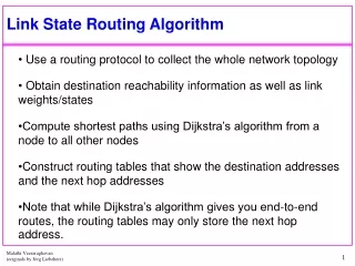
State-of-Charge Algorithm for Batteries
340 likes | 548 Views
State-of-Charge Algorithm for Batteries. Juexiao Su Zhuo Jia. Outline. 1. Brief Introduction of State-of-Charge 2. A Universal State-of-Charge Algorithm for Batteries 3. A Behavioral Algorithm for State of Charge Estimation 4.Discussion and Conclution. What is State-of-Charge.

State-of-Charge Algorithm for Batteries
E N D
Presentation Transcript
State-of-Charge Algorithm for Batteries Juexiao Su ZhuoJia
Outline 1. Brief Introduction of State-of-Charge 2.A Universal State-of-Charge Algorithm for Batteries 3.A Behavioral Algorithm for State of Charge Estimation 4.Discussion and Conclution
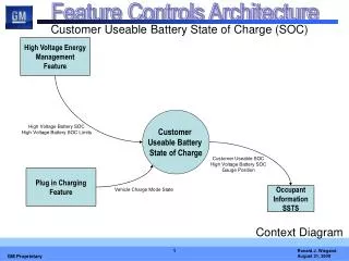
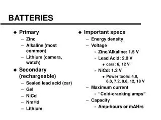
What is State-of-Charge • State of Charge (SOC): a measure of energy available in an electrochemical battery • Energy management in Hybrid Electric Vehicles (HEV) by controlling the electric motor power and gasoline engine power to: • Optimize power performance, • Reduce the emissions, • Improve the fuel economy. How to find SOC • SOC is an internal chemical state of the battery, it is not possible to measure SOC directly. • We have to develop algorithms that estimate SOC using the available physical measurements such as terminal voltage and terminal current.
Two types of SOC estimation • Coulomb-Counting Based Estimation • SoC is an integration function of time. • However, error will be accumulated over time. • Voltage-Based Estimation • Bijection between SoC and Open-Circuit Voltage (OCV) • Then how to obtain OCV from the terminal voltage and current?
Existing work on Open-Circuit-Voltage estimation Simplified circuit models applied to reduced the complexity Parameters need to be tuned for different battery types and individual battery cells predetermined to be decided
Outline 1. Brief Introduction of State-of-Charge 2.A Universal State-of-Charge Algorithm for Batteries 3.A Behavioral Algorithm for State of Charge Estimation 4.Discussion
Proposed Approach • Problem of Existing Work • Models are developed for specific types of batteries • Characteristics of Proposed Approach • Using linear system analysis but without a circuit model • Low complexity for real-time battery management • The Only Assumption Used in Proposed Approach • Within the short observing time window, a battery is treated as a time-invariant linear system and the SOC and accordingly the OCV is treated as constants.
Framework of Linear-Time-Invariant system For single input and single output system, the relationship between input and output can be represented by a deferential equation r(t) c(t) Laplace Transformation Zero-state response zero-input response
Initial time windows Assumption: Within the short observing time window, a battery is treated as a time-invariant linear system c(t) models the voltage across the battery terminal r(t) models the current entering the battery Battery
Algorithm for compute f(t) The process to calculate f(t) is very likely to the process of solving the inverse matrix
Special cases Case I: uf(t) also converges to zero as t approaches infinity. I.e., uf(t) = 0 for t > 0. Then, the terminal current is constant and the battery becomes a pure resistance network. Case II: The first sample of terminal current in the window is close to 0. Then move the window to the next sample as the starting point. The extreme case is that the sampled current is keeps 0 battery in open-circuit state.
Experiment result • The extracted SoC fits well with the simulated data (labeled as simulated) for different current profiles.
Universality • Error within 4% for different materials for active positive material / electrolyte / negative positive material of batteries (Labeled). • For each type of battery • Only a discharge from fully-charged to empty-charged is conducted to build up the bijection between OCV and SoC. • No other tuning is needed.
Robustness • The algorithm converges quickly to the correct SoC despite an upset on SoC.
Outline 1. Brief Introduction of State-of-Charge 2.A Universal State-of-Charge Algorithm for Batteries 3.A Behavioral Algorithm for State of Charge Estimation 4.Discussion and Conclusion
Behavioral Framework LTI system c(t) models the voltage across the battery terminal r(t) models the current entering the battery • We want a specific free response (zero input response) of the system. • We want to compute this free response, • directly from input and output data without constructing any model, and by making the least assumptions on the system as possible. • Behavioral framework (J.Willems, 1986) fits perfectly well to this problem! The data IS my model. Battery
LTI system representations c(t) models the voltage across the battery terminal r(t) models the current entering the battery Battery Where u(t) is input, y(t) is output
Some Definitions(Willem,1986) c(t) models the voltage across the battery terminal r(t) models the current entering the battery Battery • Definition: A discrete dynamical system is 3-tuple , with the time axis, the signal space, and the behavior. The behavior is the set of all legitimate functions, according to the system . • When the behavior is restricted to an interval [1,T], we denote the behavior as . • Definition: A . is called a trajectory. • A system is a linear when the signal space is a vector space and is a linear subspace of . • A system is time-invariant if for any where
Hankel Matrix • The L-deep block Hankel matrix of a trajectory is denoted by and defined as follows:
Fundamental Lemma(Willems et al., 2005) Let: • be a trajectory of length T of the linear time invariant system , • the system be controllable, • and the input sequence u is persistently exciting of order n+L, i.e. is full rank. • Then,
Fundamental Lemma(Willems et al., 2005 • Obvious direction: colspan : • Each column of is in B. (shift invariance) • Any linear combination of columns of is also in B (linearity, remember: B is a vector space!) • Interesting direction: colspan : Any trajectory of length L of can be written as a linear combination of columns of .
Which is free response? • Let w0 = (0; y0d ) be a free response of the system of length L. • Then by the fundamental lemma :
A Behavioral Algorithm • Solve • Then find
Notes • The battery is not an LTI system. • We are actually constructing the free response, y0 that best explains the observed data among all the LTI systems within a certain model class determined by the length of the “past”. Does it work? • Input (Terminal Current): Real current data obtained from an electrical golf cart • Output (Terminal Voltage): Simulated terminal voltage data using DualfoilSimulator • Sampling period: 6 seconds, T=500, Length of the free response computed=80.
Does it work? • l2error of Xiao et al: 0.505274 • l2 error of the Behavioral Algorithm:0.066759
Sometimes it doesn’t work. • Since the current is changing slowly, becomes "almost" rank defficient. Hence, the persistency of excitation assumption is "almost" violated and the problem becomes ill conditioned. • In this specific case, at a certain instant there is always only one singular value that is really large and the others are 6 order of magnitude smaller than the maximum singular value.
Real Data • Sampling Period=0.008 seconds, Length of the free response computed=50,T=20. • The data is provided by Hughes Research Laboratory.
Outline 1. Brief Introduction of State-of-Charge 2.A Universal State-of-Charge Algorithm for Batteries 3.A Behavioral Algorithm for State of Charge Estimation 4.Discussion
Discussion c(t) models the voltage across the battery terminal r(t) models the current entering the battery Battery System identification Data-driven method Build certain model
Reference [1]BingjunXiao, Yiyu Shi, and Lei He. A universal state-of-charge algorithm for batteries. In DAC, pages 687–692, 2010. [2]Jan W. Polderman and Jan C. Willems. Introduction to mathematical systems theory: a behavioral approach. Texts in applied mathematics, 26. Springer, 1998. [3]Ayca Balkan, Min Gao, Paulo Tabuada, Lei He. A Behavioral Algorithm for State of Charge Estimation