Download
1 / 7
70 likes | 263 Views
Customer Useable Battery State of Charge (SOC). High Voltage Energy Management Feature. Customer Useable Battery State of Charge. High Voltage Battery SOC High Voltage Battery SOC Limits. Customer Useable SOC High Voltage Battery SOC Gauge Position. Plug in Charging Feature.

E N D
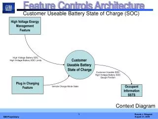
Customer Useable Battery State of Charge (SOC) High Voltage Energy Management Feature Customer Useable Battery State of Charge High Voltage Battery SOC High Voltage Battery SOC Limits Customer Useable SOC High Voltage Battery SOC Gauge Position Plug in Charging Feature Vehicle Charge Mode State Occupant Information SSTS Context Diagram
Customer Useable Battery State of Charge Customer Useable SOC Display Determine Customer Useable SOC Customer Useable SOC High Voltage Battery SOC High Voltage Battery SOC Limits Vehicle Charge Mode State High Voltage Battery SOC Gauge High Voltage Battery SOC Gauge Position Data Flow Diagram Level 0
Customer Useable Battery State of Charge Function Allocation to Subsystem
Customer Useable Battery State of Charge Primitive Specifications (PSPEC)
Customer Useable Battery State of Charge Engine Status Engine data including engine speed, engine speed status and fuel cutoff active Vehicle Speed Average Vehicle Speed Driven Propulsion System Active Powertrain indication that the propulsion system is operational and available for propulsion Propulsion System Ready Signal output to display system that vehicle is running and propulsion capable. Auto Stop Indication Signal output to display system that vehicle is in an Auto Stop (i.e. the vehicle is running and propulsion capable, but the engine is not running) Signal Definitions
Customer Useable Battery State of Charge Feature Activation Modes
Propulsion System Indication Generic Customer Interface • BCM Gateways • Engine Speed • Engine DecelFuel Cutoff • Vehicle Speed BCM IPC ECM Telltales: HSGMLAN LS GMLAN Propulsion Ready Engine Speed Engine Decel Fuel Cutoff Vehicle Speed Auto Stop Tachometer Auto Stop Mutually Exclusive Replace………………..