Link State Routing Algorithm
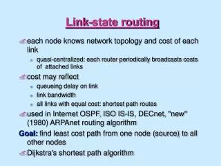
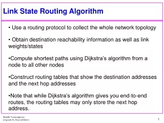
Link State Routing Algorithm. Use a routing protocol to collect the whole network topology Obtain destination reachability information as well as link weights/states Compute shortest paths using Dijkstra’s algorithm from a node to all other nodes

Link State Routing Algorithm
E N D
Presentation Transcript
Link State Routing Algorithm Use a routing protocol to collect the whole network topology Obtain destination reachability information as well as link weights/states Compute shortest paths using Dijkstra’s algorithm from a node to all other nodes Construct routing tables that show the destination addresses and the next hop addresses Note that while Dijkstra’s algorithm gives you end-to-end routes, the routing tables may only store the next hop address.
Shortest path calculations Calculate shortest paths for node s to all other nodes Dijkstra’s Algorithm: s source node. Dncost of the least-cost path from node s to node n M = {s}; for each n M Dn = dsn; while (M all nodes) do Find w M for which Dw = min{Dj ; j M}; Add w to M; for each n M Dn = minw [ Dn, Dw + dwn ]; Update route; enddo
Example Assume node 1 has obtained the entire network topology using some link state routing protocol Construct the routing table at node 1 using Dijkstra’s algorithm to determine shortest paths from node 1 to all other nodes in the network
Example (at node 1) Iteration M D1 D2 D3 D4 D5 D6 Init
Solution • Use Dijkstra’s algorithm described in slide 2 • Start with M consisting of only node 1.
Resulting Routing Tree The tree is translated into a routing table at node 1:Destination Next Hop 2 2 3 4 4 4 5 4 6 4
Link State Discussion • Each node requires complete topology information. • Link state Information must be flooded to all nodes. Guaranteed to converge. • Each node must maintain a global database. • Convergence of the algorithm is guaranteed.
IP Routing • IP Forwarding is performed by IP (in OS kernel) • IP Routing is performed by a user-level process • In Unix, by the daemon processes routed and gated
Routing Table Lookup • For each IP packet, there is one routing table lookup. 1. Find matching host address 2. Find matching network address 3. Find default entry • Routing table printout with netstat -rn • Example: Destination Gateway Flags Refcnt Use Interface 140.252.23.32 140.252.23.1 UGH 3 25000 emd0127.0.0.1 127.0.0.1 UH 1 0 lo0default 140.252.13.33 UG 0 0 emd0
Explanation of the printout • Flags: • U: route is up • G: route is to a gateway (router); if flag is not set, destination is directly connected • H: route is to a host, I.e., destination address is the complete host address; if flag is not set, route is to a network and destination address is netID or subnetID • D: route created by redirect • M: route modified by redirect • Refcnt: reference count: number of active uses of each route; for each TCP connection passing through route, this is increased by 1 • Use: number of packets sent on route • Interface: local interface
Statically Setting IP Routing Tables • There are several ways for setting IP routing tables without a routing protocol (=Static Routing) 1. Automatic creation of entry duringinitialization of a local interface (withifconfig) 2. During bootstrap with route command 3. Via ICMP redirect messages 4. Via ICMP router advertisement/router discovery messages
Route Command • Route commands are put in a system file that is read during system bootstrap • System file is: /etc/rc2.d/S69inet in Solaris, /etc/netstart in FreeBSD. • Example:“default:” destination “sun:” gateway or router 1: metric route add default sun 1route add slip bsdi 1
ICMP Redirect • Based on routing data in host, it does an arp for router 1 and sends packet to router 1 • When router 1 detects that an IP datagram should have gone to a different router, the router: • forwards the IP datagram to the correct router • sends an ICMP redirect message to the host • Host uses ICMP message to update its routing table
ICMP Router SolicitationICMP Router Advertisement • Specified in RFC 1256 (1991) • After bootstrapping a host broadcasts an ICMP router solicitation message. • In response, routers send an ICMP router advertisement message • Also, routers periodically broadcast ICMP router advertisement
Dynamic IP Routing Protocols • In Unix systems, the dynamic setting of routing tables is done by the routed or gated daemons • The routing daemons execute the following intradomain and interdomain routing protocols interdomain intradomain
RIP - Routing Information Protocol • A simple intradomain protocol • Straightforward implementation of Distance Vector Routing • Each router advertises its minimum distances to destinations every 30 seconds (or whenever its routing table changes) • RIP always uses the hop-count as link metric. Maximum hop count is 15, with “16” equal to “”. • Routes timeout after 3 minutes if they are not updated. Route metric is set to (16) and marked for deletion
Routing with RIP • This is the operation of RIP in routed. Dedicated port for RIP is UDP port 520. • Initialization: Broadcast a request packet (command = 1, metric=16; address family=0, metric=16) on the interfaces requesting current routing tables from routers. • Request received: Routers that receive above request send their entire routing table. • Response received: Update the routing table (see distance vector algorithm). • Regular routing updates: Every 30 seconds, send all or part of the routing tables to every neighbor. • Triggered Updates: Whenever the metric for a route changes, send data that has changed.
RIPv2 RIPv2 also supports multicast and provides authentication
OSPF • OSPF = Open Shortest Path First • RFC 1247 from 1991 • Alternative solution to RIP as interior gateway protocol • OSPF is a link state protocol, i.e., each node has complete topology information • OSPF messages are sent directly in IP (and not as payload of UDP packets) • Hellos and Link State Advertisements (LSAs) • To get the topology of the network • Shortest-path algorithm, e.g., Dijkstra’s to precompute routing tables.
Features of OSPF • Provides authentication of routing messages • Enables load balancing by allowing traffic to be split evenly across routes with equal cost • Supports subnetting • Supports multicasting
BGP • BGP = Border Gateway Protocol • Currently in version 4 • Note: In the context of BGP, a gateway is nothing else but an IP router that connects autonomous systems. • Interdomain routing protocol for routing between autonomous systems • Uses TCP to send routing messages • BGP is a distance vector protocol, but unlike in RIP, routing messages in BGP contain complete routes. • Network administrators can specify routing policies
BGP • BGP’s goal is to find any path (not an optimal one). Since the internals of the AS are never revealed, finding an optimal path is not feasible. • For each autonomous system (AS), BGP distinguishes: • local traffic = traffic with source or destination in AS • transit traffic = traffic that passes through the AS • Stub AS = has connection to only one AS, only carry local traffic • Multihomed AS = has connection to >1 AS, but does not carry transit traffic • Transit AS = has connection to >1 AS and carries transit traffic
135.60.81 R1 11.4.6 R2 161.6.5 180.11.22 190.4.6 Exercise .1 .1 .2 .4 .1 .1 Assume route commands in the bootstrap sequence in both routers allows them to immediately recognize their directly connected subnets Show the routing tables at nodes R1 and R2 initially before they exchange RIP messages and after. See Page 131 of your textbook for guidance.
Exercise solution Table created by route commands executed during boot-up procedure - directly-connected interfaces have a route command metric of 0 (pg. 116) but a RIP metric of 1 (pg. 131) See page 116, 114 - it states that the metric is 0 if the G flag is not set, which means a direct route. The gateway column has the IP address of the outgoing interface.
Exercise solution contd. Same as on previous slide
Exercise solution contd. • RIP messages sent. As per fig. 10.4 on page 131 of your text book each router advertises routes to each subnet on all other subnets with a hop count of 1. • Thus, each router listens to the broadcasts about the other router’s subnets. • Updated routing tables are shown on the next two slides.
Exercise solution contd. See page 131 of your textbook for RIP metrics for subnets on adjacent routers