Download
1 / 18
180 likes | 198 Views
Learn about the different types of latches and flip-flops, their operations, and how they store information. Understand bistable elements, SRLatches, and the metastable behavior of these elements.

E N D
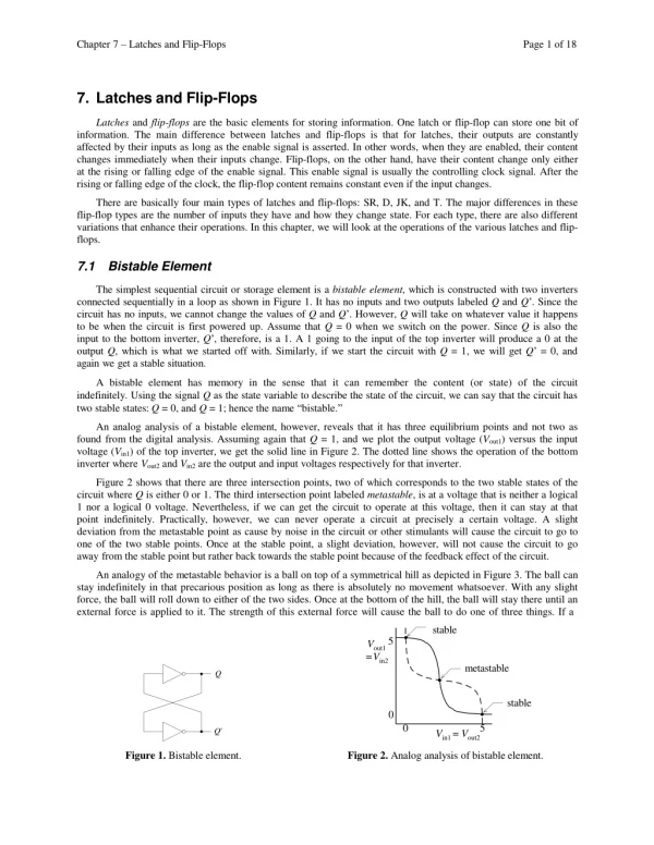
Chapter7–LatchesandFlip-Flops Page1of18 7. Latches and Flip-Flops Latchesandflip-flopsarethebasicelementsforstoringinformation.Onelatchorflip-flopcanstoreonebitof information.Themaindifferencebetweenlatchesandflip-flopsisthatforlatches,theiroutputsareconstantly affectedbytheirinputsaslongastheenablesignalisasserted.Inotherwords,whentheyareenabled,theircontent changesimmediatelywhentheirinputschange.Flip-flops,ontheotherhand,havetheircontentchangeonlyeitherattherisingorfallingedgeoftheenablesignal.Thisenablesignalisusuallythecontrollingclocksignal.Aftertherisingorfallingedgeoftheclock,theflip-flopcontentremainsconstanteveniftheinputchanges. Therearebasicallyfourmaintypesoflatchesandflip-flops:SR,D,JK,andT.Themajordifferencesintheseflip-floptypesarethenumberofinputstheyhaveandhowtheychangestate.Foreachtype,therearealsodifferent variationsthatenhancetheiroperations.Inthischapter,wewilllookattheoperationsofthevariouslatchesandflip-flops. 7.1 BistableElement Thesimplestsequentialcircuitorstorageelementisabistableelement,whichisconstructedwithtwoinvertersconnectedsequentiallyinaloopasshowninFigure1.IthasnoinputsandtwooutputslabeledQandQ’.Sincethe circuithasnoinputs,wecannotchangethevaluesofQandQ’.However,Qwilltakeonwhatevervalueithappens tobewhenthecircuitisfirstpoweredup.AssumethatQ=0whenweswitchonthepower.SinceQisalsothe inputtothebottominverter,Q’,therefore,isa1.A1goingtotheinputofthetopinverterwillproducea0attheoutputQ,whichiswhatwestartedoffwith.Similarly,ifwestartthecircuitwithQ=1,wewillgetQ’=0,andagainwegetastablesituation. Abistableelementhasmemoryinthesensethatitcanrememberthecontent(orstate)ofthecircuitindefinitely.UsingthesignalQasthestatevariabletodescribethestateofthecircuit,wecansaythatthecircuithastwostablestates:Q=0,andQ=1;hencethename“bistable.” Ananaloganalysisofabistableelement,however,revealsthatithasthreeequilibriumpointsandnottwoasfoundfromthedigitalanalysis.AssumingagainthatQ=1,andweplottheoutputvoltage(Vout1)versustheinputvoltage(Vin1)ofthetopinverter,wegetthesolidlineinFigure2.Thedottedlineshowstheoperationofthebottom inverterwhereVout2andVin2aretheoutputandinputvoltagesrespectivelyforthatinverter. Figure2showsthattherearethreeintersectionpoints,twoofwhichcorrespondstothetwostablestatesofthe circuitwhereQiseither0or1.Thethirdintersectionpointlabeledmetastable,isatavoltagethatisneitheralogical 1noralogical0voltage.Nevertheless,ifwecangetthecircuittooperateatthisvoltage,thenitcanstayatthat pointindefinitely.Practically,however,wecanneveroperateacircuitatpreciselyacertainvoltage.Aslightdeviationfromthemetastablepointascausebynoiseinthecircuitorotherstimulantswillcausethecircuittogotooneofthetwostablepoints.Onceatthestablepoint,aslightdeviation,however,willnotcausethecircuittogoawayfromthestablepointbutratherbacktowardsthestablepointbecauseofthefeedbackeffectofthecircuit. AnanalogyofthemetastablebehaviorisaballontopofasymmetricalhillasdepictedinFigure3.Theballcan stayindefinitelyinthatprecariouspositionaslongasthereisabsolutelynomovementwhatsoever.Withanyslightforce,theballwillrolldowntoeitherofthetwosides.Onceatthebottomofthehill,theballwillstaythereuntilan externalforceisappliedtoit.Thestrengthofthisexternalforcewillcausetheballtodooneofthreethings.Ifa stable Vout15 =Vin2 metastable Q stable0 05 Q' Vin1=Vout2 Figure1.Bistableelement. Figure2.Analoganalysisofbistableelement.
Chapter7–LatchesandFlip-Flops Page2of18 metastable stable stable Figure3.Ballandhillanalogyformetastablebehavior. smallforceisappliedtotheball,itwillgopartlyupthehillandthenrollsbackdowntothesameside.Ifabig enoughforceisappliedtoit,itwillgooverthetopanddowntheothersideofthehill.Wecanalsoapplyaforce thatisjuststrongenoughtopushtheballtothetopofthehill.Againatthisprecariousposition,itcanrolldown eitherside. Wewillfindthatalllatchesandflip-flopshavethismetastablebehavior.Inorderfortheelementtochangestate,weneedtoapplyastrongenoughpulsesatisfyingagivenminimumwidthrequirement.Otherwise,the elementwilleitherremainatthecurrentstateorgointothemetastablestateinwhichcaseunpredictableresultscan occur. 7.2SRLatch Thebistableelementisabletorememberorstoreonebitofinformation.However,becauseitdoesnothaveanyinputs,wecannotchangetheinformationbitthatisstoredinit.Inordertochangetheinformationbit,weneedtoaddinputstothecircuit.ThesimplestwaytoaddinputsistoreplacethetwoinverterswithtwoNANDgatesas showninFigure4(a).ThiscircuitiscalledaSRlatch.InadditiontothetwooutputsQandQ',therearetwoinputsS'andR'forsetandresetrespectively.Followingtheconvention,theprimeinS andR denotesthattheseinputsare activelow.TheSRlatchcanbeinoneoftwostates:asetstatewhenQ=1,oraresetstatewhenQ=0. TomaketheSRlatchgotothesetstate,wesimplyasserttheS'inputbysettingitto0.Rememberthat0NAND anythinggivesa1,henceQ=1andthelatchisset.IfR'isnotasserted(R'=1),thentheoutputofthebottomNANDgatewillgivea0,andsoQ'=0.ThissituationisshowninFigure4(d)attimet0.Ifwede-assertS'sothatS'=R'= 1,thelatchwillremainatthesetstatebecauseQ',thesecondinputtothetopNANDgate,is0whichwillkeepQ=1 asshownattimet1.Attimet2weresetthelatchbymakingR'=0.Now,Q'goesto1andthiswillforceQtogotoa 0.Ifwede-assertR'sothatagainwehaveS'=R'=1,thistimethelatchwillremainattheresetstateasshownattimet3.Noticethetwotimes(att1andt3)whenbothS'andR'arede-asserted.Att1,Qisata1,whereas,att3,Qisat S' Q Q' R' (a) (b) S' R' Undefined Q Undefined Q' t0t1t2t3t4t5 (d) t6 (c) Figure4. SRlatch:(a)circuitusingNANDgates;(b)truthtable;(c)logicsymbol;(d)timingdiagram.
Chapter7–LatchesandFlip-Flops Page3of18 R Q Q' S (b) (c) (a) Figure5.SRlatch:(a)circuitusingNORgates;(b)truthtable;(c)logicsymbol. a0.Whenbothinputsarede-asserted,theSRlatchmaintainsitspreviousstate.Previoustot1,Qhasthevalue1,soatt1,Qremainsata1.Similarly,previoustot3,Qhasthevalue0,soatt3,Qremainsata0. IfbothS'andR'areasserted,thenbothQandQ'areequalto1asshownattimet4.Ifoneoftheinputsignalsisde-assertedearlierthantheother,thelatchwillendupinthestateforcedbythesignalthatwasde-assertedlaterasshownattimet5.Att5,R'isde-assertedfirst,sothelatchgoesintothenormalsetstatewithQ=1andQ'=0. AproblemexistsifbothS'andR'arede-assertedatexactlythesametimeasshownattimet6.Ifbothgateshaveexactlythesamedelaythentheywillbothoutputa0atexactlythesametime.Feedingthezerosbacktothegate inputwillproducea1,againatexactlythesametime,whichagainwillproducea0,andsoonandon.Thisoscillatingbehavior,calledthecriticalrace,willcontinueforever.Ifthetwogatesdonothaveexactlythesamedelaythenthesituationissimilartode-assertingoneinputbeforetheother,andsothelatchwillgointoonestateortheother.However,sincewedonotknowwhichisthefastergate,therefore,wedonotknowwhichstatethelatchwillgointo.Thus,thelatch’snextstateisundefined. Inordertoavoidthisindeterministicbehavior,wemustmakesurethatthetwoinputsareneverde-assertedatthesametime.Notethatbothofthemcanbede-asserted,butjustnotatthesametime.Inpractice,thisisguaranteedbynothavingbothofthemasserted.Anotherreasonwhywedonotwantbothinputstobeassertedisthatwhenthey arebothasserted,QisequaltoQ',butweusuallywantQtobetheinverseofQ'. SS' Q E Q' R R' (a) (b) E S R Undefined Q Undefined Q' t0 t1 t2 (c) (d) Figure6. SRlatchwithenable:(a)circuitusingNANDgates;(b)truthtable;(c)logicsymbol;(d)timing diagram.
Chapter7–LatchesandFlip-Flops Page4of18 R R Q E Q' S S (a) (b) SRlatchwithenable:(a)circuitusingNORgates;(b)truthtable. Figure7. • Fromtheaboveanalysis,weobtainthetruthtableinFigure4(b)fortheNANDimplementationoftheSRlatch.QisthecurrentstateorthecurrentcontentofthelatchandQnextisthevaluetobeupdatedinthenextstate.Figure4(c)showsthelogicsymbolfortheSRlatch. • TheSRlatchcanalsobeimplementedusingNORgatesasshowninFigure5(a).ThetruthtableforthisimplementationisshowninFigure5(b).Fromthetruthtable,weseethatthemaindifferencebetweenthisimplementationandtheNANDimplementationisthatfortheNORimplementation,theS andR inputsareactivehigh,sothatsettingS to1willsetthelatchandsettingR to1willresetthelatch.However,justliketheNANDimplementation,thelatchissetwhenQ=1andresetwhenQ=0.ThelatchremembersitspreviousstatewhenS=R • =0.WhenS=R=1,bothQandQ'are0.ThelogicsymbolfortheSRlatchusingNORimplementationisshowninFigure5(c). • SR Latch with Enable • TheSRlatchissensitivetoitsinputsallthetime.Itissometimesusefultobeabletodisabletheinputs.TheSR latchwithenable(alsoknownasagatedSRlatch)accomplishesthisbyaddinganenableinput,E,totheoriginalimplementationofthelatchthatallowsthelatchtobeenabledordisabled.ThecircuitfortheSRlatchwithenableusingNANDgatesisshowninFigure6(a),itstruthtableinFigure6(b),andlogicsymbolinFigure6(c).WhenE= 1,thecircuitbehaveslikethenormalNANDimplementationoftheSRlatchexceptthattheSandRinputsareactive highratherthanlow.WhenE =0,thelatchremainsinitspreviousstateregardlessoftheS andR inputs.Inactual circuits,theenableinputcaneitherbeactivehighorlow,andmaybenamedENABLE,CLK,orCONTROL.AtypicaloperationofthelatchisshowninthetimingdiagraminFigure6(d).Betweent0andt1,E=0sochangingtheSandR inputsdonotaffecttheoutput.Betweent1andt2,E=1andthetraceissimilartothetraceofFigure4(d)exceptthat theinputsignalsareinverted. • TheSRlatchwithenablecanalsobeimplementedusingNORgatesasshownFigure7. • D Latch Q Q (c) Q' Q' D D (a)(b) (d) Figure8. Dlatch:(a)circuitusingNANDgates;(b)circuitusingNORgates;(c)truthtable;(d)logicsymbol.
Chapter7–LatchesandFlip-Flops Page5of18 S D Q E Q'R (b) (a) E D Q Q' t0 t1 t2 t3 (c) (d) Figure9. Dlatchwithenable:(a)circuitusingNANDgates;(b)truthtable;(c)logicsymbol;(d)timing diagram. • ThedisadvantagewiththeSRlatchisthatweneedtoensurethatthetwoinputs,SandR,areneverde-assertedatthesametime.ThissituationispreventedintheDlatchbyaddinganinverterbetweentheoriginalSandRinputsandreplacingthemwithjustoneinputD(fordata)asshowninFigure8(a)and(b). • NoticethattheplacementoftheinverterwithrespecttotheQoutputissuchthattheQoutputvaluefollowstheD input.Thisfeatureisusefulbecause,whereastheSRlatchisusefulforsettingorresettingaflagonagivencondition,theDlatchisusefulforsimplystoringabitofinformationthatispresentedonaline.Figure8(c)showsthetruthtablefortheDlatch,andFigure8(d)showsthegraphicsymbol. • DLatchwithEnable • JustliketheSRlatchwithanenableinput,theDlatchcanalsohaveanenableinputasshowninFigure9(a).WhentheEinputisasserted(E=1),theQoutputfollowstheDinput.Inthissituation,thelatchissaidtobe“open” andthepathfromtheinputDtotheoutputQis“transparent”.Hencethecircuitisoftenreferredtoasatransparentlatch.WhenE isde-asserted(E =0),thelatchisdisabledor“closed”,andtheQ outputretainsitslastvalue independentoftheDinput.AsampletimingdiagramfortheoperationoftheDlatchwithenableisshowninFigure 9(d).Betweent0andt1,thelatchisenabledwithE =1sotheoutputQ followstheinputD.Betweent1andt2,the latchisdisabled,soQremainsstableevenwhenDchanges. • DFlip-Flop • Latchesareoftencalledlevel-sensitivebecausetheiroutputfollowstheirinputsaslongastheyareenabled.Theyaretransparentduringthisentiretimewhentheenablesignalisasserted.Therearesituationswhenitismoreusefultohavetheoutputchangeonlyattherisingorfallingedgeoftheenablesignal.Thisenablesignalisusuallythecontrollingclocksignal.Thus,wecanhaveallchangessynchronizedtotherisingorfallingedgeoftheclock.Anedge-triggeredflip-flopachievesthisbycombininginseriesapairoflatches.Figure10(a)showsapositive- edge-triggeredDflip-flopwheretwoDlatchesareconnectedinseriesandaclocksignalClkisconnectedtotheE inputofthelatches,onedirectly,andonethroughaninverter.Thefirstlatchiscalledthemasterlatch.ThemasterlatchisenabledwhenClk=0andfollowstheprimaryinputD.WhenClkisa1,themasterlatchisdisabledbutthesecondlatch,calledtheslavelatch,isenabledsothattheoutputfromthemasterlatchistransferredtotheslave latch.TheslavelatchisenabledallthewhilethatClk=1,butitscontentchangesonlyatthebeginningofthecycle, thatis,onlyattherisingedgeofthesignalbecauseonceClkis1,themasterlatchisdisabledandsotheinputtothe
Chapter7–LatchesandFlip-Flops Page6of18 slavelatchwillnotchange.ThecircuitofFigure10(a)iscalledapositiveedge-triggeredflip-flopbecausetheoutputQontheslavelatchchangesonlyattherisingedgeoftheclock.Iftheslavelatchisenabledwhentheclockislow, thenitisreferredtoasanegativeedge-triggeredflip-flop.ThecircuitofFigure10(a)isalsoreferredtoasamaster- slaveDflip-flopbecauseofthetwolatchesusedinthecircuit.Figure10(b)and(c)showthetruthtableandthe logicsymbolrespectively.Figure10(d)showsthetimingdiagramfortheDflip-flop.
Chapter7–LatchesandFlip-Flops Page7of18 Anotherwayofconstructingapositive-edge-triggeredflip-flopistousethreeinterconnectedSRlatchesrather thanamasterandslaveDlatchwithenable.ThecircuitisshowninFigure11.Theadvantageofthiscircuitisthatitusesonly6NANDgates(26transistors)asopposedto10gates(46transistors)forthemaster-slaveDflip-flopofFigure10(a).Theoperationofthecircuitisasfollows.WhenE=0,theoutputsofgates2and3arehigh(0NANDx =1).Thusn2=n3=1,whichmaintainstheoutputlatch,comprisinggates5and6,initscurrentstate.Atthesametimen4=D'sinceoneinputtogate4isn3whichisa1(1NANDx=x').Similarly,n1=D.WhenEchangesto1,n2 willbeequalton1'=D',whilen3willbeequaltoD.SoifD=0,thenn3willbe0,thusassertingR'andresettingtheoutputlatchQto0.Ontheotherhand,ifD=1,thenn2willbe0,thusassertingS'andsettingtheoutputlatchQto1. OnceE=1,changingDwillnotchangen2orn3,soQwillremainstableduringtheremainingtimethatEisasserted. QMD D DQ E Master Q Q E Q'Q' Slave Clk (a) (b) (c) Figure10. Master-slavepositive-edge-triggeredDflip-flop:(a)circuitusingDlatches;(b)truthtable;(c)logicsymbol;(d)timingdiagram. Setlatch 1 n 1 S' 2 n2 5 Q Clk 6 Q' R' 3 n 3 Outputlatch n4 4 D Resetlatch Figure11.Positive-edge-triggeredDflip-flop.
Chapter7–LatchesandFlip-Flops Page8of18 D D Q Qa E Clk Q' DQ ClkQ' Qb Clk D Qa Qb DQ ClkQ' Qc Q c (a)(b) Comparisonofagatedlatch,apositive-edge-triggeredflip-flop,andanegative-edge-triggeredflip-flop:(a)circuit;(b)timingdiagram. Figure12. Figure12comparesthedifferentoperationsbetweenalatchandaflip-flop.In(a),wehaveagatedDlatch,apositive-edge-triggeredDflip-flopandanegative-edge-triggeredDflip-flop,allhavingthesameD inputandcontrolledbythesameclocksignal.(b)showsasampletraceofthecircuit’soperations.NoticethatthegatedDlatchQafollowstheD inputaslongastheclockishigh.Thepositive-edge-triggeredflip-flopQbrespondstotheD inputonlyattherisingedgeoftheclockwhilethenegative-edge-triggeredflip-flopQcrespondstotheDinputonlyatthefallingedgeoftheclock. 7.7 D Flip-Flop with Enable AcommonlydesiredfunctioninDflip-flopsistheabilitytoholdthelastvaluestoredratherthanloadinanewvalueattheclockedge.ThisisaccomplishedbyaddinganenableinputcalledEN orCE (clockenable)throughamultiplexerasshowninFigure13(a).WhenEN =1,theprimaryD signalwillpasstotheD inputoftheflip-flop,thusupdatingthecontentoftheflip-flop.WhenEN=0,thebottomANDgateisenabledandsothecurrentcontentoftheflip-flop,Q,ispassedbacktotheinput,thus,keepingitscurrentvalue.Noticethatchangestotheflip-flopvalueoccuronlyattherisingedgeoftheclock.ThetruthtableandthelogicsymbolfortheDflip-flopwithenabled isshownin(b)and(c)respectively. D EN DQ ClkQ' Q Clk Q' (c) (a) (b) Figure13.Dflip-flopwithenable:(a)circuit;(b)truthtable;(c)logicsymbol.
Chapter7–LatchesandFlip-Flops Page9of18 7.8AsynchronusInputs Flip-flops,aswehaveseensofar,changestatesattheedgeofasynchronizingclocksignal.Manycircuitsrequiretheinitializationofflip-flopstoaknownstateindependentoftheclocksignal.Sequentialcircuitsthatchangestateswheneverachangeininputvaluesoccursindependentoftheclockarereferredtoasasynchronoussequentialcircuits.Synchronoussequentialcircuits,ontheotherhand,changestatesonlyattheedgeoftheclock signal.Asynchronousinputsareusuallyavailableforbothflip-flopsandlatches,andtheyareusedtoeithersetor clearthestorageelement’scontentindependentoftheclock. Figure14(a)showsaDlatchwithasynchronousPRESET'andCLEAR'inputs,and(b)isthelogicsymbolforit.(c) isthecircuitfortheDedge-triggeredflip-flopwithasynchronousPRESET'andCLEAR'inputs,and(d)isthelogicsymbolforit.WhenPRESET'isasserted(setto0)thecontentofthestorageelementissettoa1immediately,andwhenCLEAR'isasserted(setto0)thecontentofthestorageelementissettoa0immediately. Preset' S D Q E Q'R Clear' (a) (b) Preset' Q Clk Q' D Clear' (c)(d) Figure14.Storageelementswithasynchronousinputs:(a)Dlatchwithpresetandclear;(b)logicsymbolfor(a); (c)Dedge-triggeredflip-flopwithpresetandclear;(d)logicsymbolfor(c). 7.9Flip-FlopTypes Therearebasicallyfourmaintypesofflip-flops:SR,D,JK,andT.Themajordifferencesintheseflip-floptypesareinthenumberofinputstheyhaveandhowtheychangestate.Eachtypecanhavedifferentvariationssuch asactivehighorlowinputs,whethertheychangestateattherisingorfallingedgeoftheclocksignal,andwhethertheyhaveasynchronousinputsornot.Theflip-flopscanbedescribedfullyanduniquelybyitslogicsymbol, characteristictable,characteristicequation,statediagram,orexcitationtable,andaresummarizedinFigure15.
Chapter7–LatchesandFlip-Flops Page10of18 Figure15.Flip-floptypes.
Chapter7–LatchesandFlip-Flops Page11of18 7.9.1 SR Flip-Flop WecanreplacetheDlatchesintheDflip-flopofFigure10(a)withSRlatchestogetamaster-slaveSRflip-flopshowninFigure16.LikeSRlatches,SRflip-flopsareusefulincontrolapplicationswherewewanttobeabletosetorresetthedatabit.However,unlikeSRlatches,SRflip-flopschangetheircontentonlyattheactiveedgeof theclocksignal.SimilartoSRlatches,SRflip-flopscanenteranundefinedstatewhenbothinputsareassertedsimultaneously. S E R S E R Q Q S Q Q' Q' R Q' Clk (c) (a) (b) Figure16.SRflip-flop:(a)circuit;(b)truthtable;(c)logicsymbol. 7.9.2 JK Flip-Flop JKflip-flopsareverysimilartoSRflip-flops.TheJinputisjustliketheSinputinthatwhenasserted,itsetstheflip-flop.Similarly,theK inputisliketheRinputwhereitclearstheflip-flopwhenasserted.Theonlydifferenceiswhenbothinputsareasserted.FortheSRflip-flop,thenextstateisundefined,whereas,fortheJKflip-flop,thenext stateistheinverseofthecurrentstate.Inotherwords,theJKflip-floptogglesitsstatewhenbothinputsareasserted.Thecircuit,truthtableandthelogicsymbolfortheJKflip-flopisshowninFigure17. J K DQ ClkQ' Q Q' Clk (a) (c) (b) Figure17.JKflip-flop:(a)circuit;(b)truthtable;(c)logicsymbol. 7.9.3 TFlip-Flop TheTflip-flophasoneinputinadditiontotheclock.T standsfortogglefortheobviousreason.WhenT is asserted(T=1),theflip-flopstatetogglesbackandforth,andwhenTisde-asserted,theflip-flopkeepsitscurrent state.TheTflip-flopcanbeconstructedusingaDflip-flopwiththetwooutputsQandQ'feedbacktotheD inputthroughamultiplexerthatiscontrolledbytheTinputasshowninFigure18.
Chapter7–LatchesandFlip-Flops Page12of18 DQ ClkQ' Q T Q' Clk (c) (b) (a) Figure18.Tflip-flop:(a)circuit;(b)truthtable;(c)logicsymbol. 7.9.4 Logic Symbol Thelogicorgraphicalsymboldescribestheflip-flop’sinputsandoutputs,thenamesgiventothesesignals,andwhethertheyareactivehighorlow.Alltheflip-flopshaveQ andQ'astheiroutputs.AllofthemalsohaveaCLKinput.Thesmalltriangleattheclockinputindicatesthatthecircuitisaflip-flopandsoitistriggeredbytheedgeof theclocksignal;ifthereisacircleinfront,thenitisthefallingedge,otherwise,itistherisingedgeoftheclock T Q Clk Q' (a)(b)(c)(d) Figure19.Variouslogicsymbols:(a)ActivelowSRlatch;(b)positive-edge-triggeredactive highTflip-flop;(c)negative-edge-triggeredTflip-flop;(d)positive-edge-triggered Dflip-flopwithasynchronousactivelowpresetandclear. signal.Withoutthesmalltriangle,thecircuitisalatch.Inaddition,theflip-flopshaveoneortwomoreinputsthatcharacterizetheflip-flopandgiveititsname.Figure19showsseveralsamplelogicsymbolsforvariousmemory elements. 7.9.5 CharacteristicTable Thecharacteristictableisjustthetruthtablebutusuallywritteninashorterformat.Forexample,comparethecharacteristictablefortheJKflip-flopinFigure20withthetruthtableinFigure17(b).Thetruthtable,aswehave seen,simplylistsallpossiblecombinationsoftheinputsignals,thecurrentstate(orcontent)oftheflip-flop,andthe nextstatethattheflip-flopwillgotoatthenextactiveedgeoftheclocksignal.Thecharacteristictableanswersthe questionofwhatisthenextstatewhengiventheinputsandthecurrentstate,andisusedintheanalysisofsequentialcircuits. Figure20.JKflip-flopcharacteristictable.
Chapter7–LatchesandFlip-Flops Page13of18 7.9.6 Characteristic Equation ThecharacteristicequationisthefunctionalBooleanequationthatisderivedfromthecharacteristictable.Thisequationformallydescribesthefunctionalbehavioroftheflip-flop.Likethecharacteristictable,itspecifiestheflip-flop’snextstateasafunctionofitscurrentstateandinputs.Forexample,thecharacteristicequationfortheJKflip-flopcanbederivedfromthetruthtableasfollows: =J'K'Q+JK'Q+JK'Q'+JKQ' =K'Q(J'+J)+JQ'(K'+K) =K'Q+JQ' Qnext ThecharacteristicequationcanalsobeobtainedfromthetruthtableusingtheK-mapmethodasfollowsforthe SRflip-flop: RQ 00011110 S R'QS 0 1 Thus,thecharacteristicequationfortheSRflip-flopis =S+R'Q. Qnext • StateDiagram • Astatediagramisagraphthatshowstheflip-flop’soperationsintermsofhowittransitionsfromonestatetoanother.Thenodesarelabeledwiththestatesandthedirectedarcsarelabeledwiththeinputsignalsthatcausethe transitiontogofromonestatetothenext.Figure21showsthestatediagramfortheSRflip-flop.Forexample,togofromstateQ =0tothestateQ =1,thetwoinputsS andR havetobe1and0respectively.Similarly,ifthecurrent stateisQ=0andwewanttoremaininthatstate,thenSRneedtobe00or01. • SR=10SR=00or01 • Q=0Q=1 • SR=00or10SR=01 • Figure21.StatediagramfortheSRflip-flop. • ExcitationTable • Theexcitationtablegivesthevalueoftheflip-flop’sinputsthatarenecessarytochangetheflip-flop’scurrent statetothedesirednextstateatthenextactiveedgeoftheclocksignal.Theexcitationtableanswersthequestionofwhatshouldtheinputsbewhengiventhecurrentstatethattheflip-flopisinandthenextstatethatwewanttheflip-floptogoto.Thistableisusedinthesynthesisofsequentialcircuits.
Chapter7–LatchesandFlip-Flops Page14of18 Figure22showstheexcitationtablefortheSRflip-flop.Ascanbeseen,thistablecanbeobtaineddirectlyfromthestatediagram.Forexample,ifthecurrentstateisQ=0andwewantthenextstatetobeQ=1,thenthetwoinputsmustbeSR=10. Figure22.SRflip-flopexcitationtable. 7.10VHDLforLatchesandFlip-Flops 7.10.1ImpliedMemoryElement VHDLdoesnothaveanyexplicitobjectfordefiningamemoryelement.Instead,thesemanticsofthelanguage providesforsignalstobeinterpretedasamemoryelement.Inotherwords,memoryelementisdeclareddepending onhowthesesignalsareassigned.ConsiderthecodeinFigure23. ENTITYno_memory_elementIS PORT(A,B:INSTD_LOGIC; C:OUTSTD_LOGIC); ENDno_memory_element; ARCHITECTUREBehaviorOFno_memory_elementIS BEGIN PROCESS(A,B) BEGIN C<='1';--assignsdefaultvaluetoC IFA=BTHEN C<='0'; ENDIF; ENDPROCESS; ENDBehavior; Figure23.SampleVHDLdescriptionofacombinationalcircuit. Theprocessassignsthedefaultvalueof1toCandthenifAisequaltoBthenitchangesthevalueofCtoa0.Inthiscode,CwillbeassignedavalueforallpossibleoutcomesofthetestA=B.Withthisconstruct,a combinationalcircuitisproduced. IfwesimplyremovethestatementthatassignsthedefaultvaluetoC,thenwehaveasituationwherenovaluewillbeassignedtoCifAisnotequaltoB.ThekeypointhereisthattheVHDLsemanticsstipulatethatincaseswherethecodedoesnotspecifyavalueofasignal,thesignalshouldretainitscurrentvalue.Inotherwords,the signalmustrememberitscurrentvalue,andinordertodoso,amemoryelementisimplied.
Chapter7–LatchesandFlip-Flops Page15of18 • VHDLCodeforaD Latch • Figure24showstheVHDLcodeforaDlatchwithenable.IfEnableis1thenQfollowsD.However,ifEnableisnot1,thecodedoesnotspecifywhatQshouldbe,therefore,Qretainsitscurrentvalue.Thiscodeproducesalatch andnotaflip-flopbecauseQfollowsD aslongasEnableis1,andnotonlyattheactiveedgeofthesignal.TheprocesssensitivitylistincludesbothDandEnablebecauseeitheroneofthesesignalscancauseachangeinthevalue oftheQoutput. • LIBRARYieee; • USEieee.std_logic_1164.all; • ENTITYD_latch_with_enableIS PORT(D,Enable:INSTD_LOGIC; • Q:OUTSTD_LOGIC); • ENDD_latch_with_enable; • ARCHITECTUREBehaviorOFD_latch_with_enableIS BEGIN • PROCESS(D,Enable) BEGIN • IFEnable='1'THEN • Q<=D; ENDIF; • ENDPROCESS; • ENDBehavior; • Figure24.VHDLcodeforagatedDlatch. • VHDLCodefor a D Flip-Flop • Figure25showsthebehavioralVHDLcodeforapositive-edge-triggeredDflip-flop.TheonlydifferencehereisthatQfollowsDonlyattherisingedgeoftheclock,anditisspecifiedherebythecondition“Clock’EVENTANDClock='1'.”The’EVENTattributereferstoanychangesinthequalifyingclocksignal.Sowhenthishappensandtheresultingclockvalueisaone,wehaveineffect,aconditionforapositiveorrisingclockedge.Notealsothatthe processsensitivitylistcontainsonlytheclocksignalbecauseitistheonlysignalthatcancauseachangeintheQ output. • LIBRARYieee; • USEieee.std_logic_1164.all; • ENTITYD_flipflopIS • PORT(D,Clock:INSTD_LOGIC; Q:OUTSTD_LOGIC); • ENDD_flipflop; • ARCHITECTUREBehaviorOFD_flipflopIS BEGIN • PROCESS(Clock) BEGIN • IFClock’EVENTANDClock='1'THEN • Q<=D; ENDIF; • ENDPROCESS; • ENDBehavior; • Figure25.VHDLcodeforapositive-edge-triggeredDflip-flopusinganIFstatement.
Chapter7–LatchesandFlip-Flops Page16of18 Anotherwaytodescribeaflip-flopistousetheWAITstatementinsteadoftheIFstatementasshowninFigure 26.WhenexecutionreachestheWAITstatement,itstopsuntiltheconditioninthestatementistruebefore proceeding.NotealsothattheprocesssensitivitylistisomittedbecausetheWAITstatementimpliesthatthe sensitivitylistcontainsonlytheclocksignal. LIBRARYieee; USEieee.std_logic_1164.all; ENTITYD_flipflopIS PORT(D,Clock:INSTD_LOGIC; Q:OUTSTD_LOGIC); ENDD_flipflop; ARCHITECTUREBehaviorOFD_flipflopIS BEGIN PROCESS BEGIN WAITUNTILClock’EVENTANDClock='0' Q<=D; ENDPROCESS; ENDBehavior; --negativeedgetriggered Figure26.VHDLcodeforanegative-edge-triggeredDflip-flopusingaWAITstatement. Alternatively,wecanwriteastructuralVHDLdescriptionforthepositive-edge-triggeredDflip-flopasshown inFigure27.ThisVHDLcodeisbasedonthecircuitforapositive-edge-triggeredDflip-flopasgiveninFigure11. --definethebehavioraloperationofthe2-inputNANDgate LIBRARYieee; USEIEEE.std_logic_1164.all; ENTITYNAND2IS PORT(I0,I1:INSTD_LOGIC; O:OUTSTD_LOGIC); ENDNAND2; ARCHITECTUREBehavioral_NAND2OFNAND2IS BEGIN O<=I1NANDI2; ENDBehavioral_NAND2; --definethebehavioraloperationofthe3-inputNANDgate LIBRARYieee; USEIEEE.std_logic_1164.all; ENTITYNAND3IS PORT(I0,I1,I2:INSTD_LOGIC; O:OUTSTD_LOGIC); ENDNAND3; ARCHITECTUREBehavioral_NAND3OFNAND3IS BEGIN O<=NOT(I1ANDI2ANDI3); ENDBehavioral_NAND3; Figure27.StructuralVHDLcodeforapositive-edge-triggeredDflip-flop.
Chapter7–LatchesandFlip-Flops Page17of18 --definethestructuraloperationoftheSRlatch LIBRARYieee; USEIEEE.std_logic_1164.all; ENTITYSRlatchIS PORT(SN,RN:INSTD_LOGIC; Q,QN:OUTSTD_LOGIC); ENDSRlatch; ARCHITECTUREStructural_SRlatchOFSRlatchIS COMPONENTNAND2PORT(I0,I1:INSTD_LOGIC; O:OUTSTD_LOGIC); ENDCOMPONENT; BEGIN U1:NAND2PORTMAP(SN,QN,Q); U2:NAND2PORTMAP(Q,RN,QN); ENDStructural_SRlatch; --definethestructuraloperationofthepositiveedgetriggered --Dflip-flop LIBRARYieee; USEIEEE.std_logic_1164.all; ENTITYpositive_edge_triggered_D_flipflopIS PORT(D,Clock:INSTD_LOGIC; Q,QN:OUTSTD_LOGIC); ENDpositive_edge_triggered_D_flipflop; ARCHITECTUREStructuralOFpositive_edge_triggered_D_flipflopIS SIGNALN1,N2,N3,N4:STD_LOGIC; COMPONENTSRlatchPORT(SN,RN:INSTD_LOGIC; Q,QN:OUTSTD_LOGIC); ENDCOMPONENT; COMPONENTNAND2PORT(I0,I1:INSTD_LOGIC; O:OUTSTD_LOGIC); ENDCOMPONENT; COMPONENTNAND3PORT(I0,I1,I2:INSTD_LOGIC; O:OUTSTD_LOGIC); ENDCOMPONENT; BEGIN U1:SRlatchPORTMAP(N4,Clock,N1,N2); U2:SRlatchPORTMAP(N2,N3,Q,QN); U3:NAND3PORTMAP(N2,Clock,N4,N3); U4:NAND2PORTMAP(N3,D,N4); ENDStructural; --setlatch --outputlatch --resetlatch Figure27(continue).StructuralVHDLcodeforapositive-edge-triggeredDflip-flop.
Chapter7–LatchesandFlip-Flops Page18of18 7.10.4VHDLCodeforaD Flip-FlopwithAsynchronousInputs FigureshowstheVHDLcodeforapositive-edge-triggeredDflip-flopwithasynchronousactivelowresetand clearinputs.Thetwoasynchronousinputsarecheckedforindependentlyoftheclockevent.WheneithertheResetortheClearinputisasserted,Qissettoa1or0respectivelyimmediately.OtherwiseQfollowsDattherisingedge oftheclock. LIBRARYieee; USEieee.std_logic_1164.all; ENTITYD_flipflopIS PORT(D,Clock,Reset,Clear:INSTD_LOGIC; Q:OUTSTD_LOGIC); ENDD_flipflop; ARCHITECTUREBehaviorOFD_flipflopIS BEGIN PROCESS(Clock,Reset,Clear) BEGIN IFReset='0'THEN Q<='1'; ELSIFClear='0'THEN Q<='0'; ELSIFClock’EVENTANDClock='1'THEN Q<=D; ENDIF; ENDPROCESS; ENDBehavior; Figure28.VHDLcodeforaDflip-flopwithasynchronousinputs.