Download
1 / 31
310 likes | 341 Views
This article discusses the specific recommendations made by the MWG (Materials Work Group) meeting held at UCLA in 2006 regarding the coordination of modeling and experimental work for HAPL (High Average Power Laser) materials. The focus is on the ORNL (Oak Ridge National Laboratory) contribution to this work, including guidelines for handling and testing tungsten, as well as the investigation of thermal fatigue and carbon implantation effects. Relevant topics include surface thermomechanics, IR thermal fatigue, development of VPS W (Vapor Phase Sintered Tungsten) LAF (Liquid-Armor Fusion), and helium release experiments.

E N D
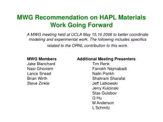
MWG Recommendation on HAPL Materials Work Going Forward A MWG meeting held at UCLA May 15,16 2006 to better coordinate modeling and experimental work. The following includes specifics related to the ORNL contribution to this work. MWG Members Additional Meeting Presenters Jake Blanchard Tim Renk Nasr Ghoniem Farrokh Najmabadi Lance Snead Nalin Parikh Brian Wirth Shahram Sharafat Steve Zinkle Jeff Latkowski Jerry Kulcinski Stas Gulobov Q Hu M Anderson L Schmitz
Surface Thermomechanics • Goal : Common experimental plan for all irradiation facilities • Experimental Controls : • Follow Guidance for Handling and Testing of Tungsten • Common sample size (20x20 or 20x10 mm) • Measurements Standardized and Applied: • Surface Morphology • Roughness (peak to valley and characteristic wavelength) • Crack Density (surface electrical resistivity, TEM) • Mass Loss • Key question: Do mass loss and surface roughness/topology saturate with fluence?
Handling of Tungsten • Cleaning : Prior to experiments the tungsten should be soaked in an ultrasonic bath of research grade acetone for about ten minutes. The acetone bath should be immediately followed by an ultrasonic bath of ethanol (five minutes.) The samples should be covered and air dried. Prior to use samples should be blown clean with compressed air or other moisture-free gas. • Do not use cotton, kleenex or q-tips to dry the surface. Cotton in particular is bad for surface scratching. • Samples should be baked out prior to testing. Typically, 200°C for 30 minutes is fine. Do not allow tungsten to be heated in vacuum poorer than 10-4 Torr. For experiments that are actively heated this can be the first step. • Foam samples must be thoroughly outgassed prior to testing and preferably stored in a desiccator. • Testing of tungsten should be carried out in as high a vacuum as possible. Greater than 10-4 Torr is required. If testing can not be carried out in the 10-6 Torr range then moisture and oxygen sensors are required. • Samples must be firmly attached to heat sink with refractory materials (I.e. TZM moly mask and bolt arrangement.)
IR Thermal Fatigue (ORNL) • Exposure of single crystal tungsten following sample handling procedure to determine level of atmospheric pick-up. • Base temperature of 600°C. • Verify interface temperatures. • Complete upgrade to continuous operation. • Carry out thermal fatigue of carbon implanted VPS materials.
IFE ~104 MW/m2 300kW Upgrade ~10 msec ~200 MW/m2 ~2 msec ~0.1 MJ/m2 300kW Current ~35 MW/m2 ~0.4 MJ/m2 ~20 msec 750kW Current ~0.7 MJ/m2 ~5 MW/m2 ~0.1 MJ/m2 ~20 msec Update: IR Thermal Fatigue (ORNL) • Software for continuous operation being installed. • Very high cycle testing of VPS W/LAF on hold.
Development of VPS W/LAF O C Interface F82H Steel Tungsten 20.0keV 10.0kX 1.0 µm • We are considering the VPS W/LAF sufficiently mature. Have withstood 10,000. • Continuing long term aging of interface (currently > 10,000hr) • Next series of thermal fatigue tests planned for long-term aged and carbon implanted material.
Useable Beam Waist (Ø = 1.13 cm) Tungsten Target w/ Melt Blocks (1-2mm thick) Molybdenum Clamping Disks (1-2mm thick ea) Quick Response Thermocouple (Under Development) Ceramic Resistive Heating Element (12A, 250W) Molybdenum Cap (λ = 138 W/mK) High Conductivity Wire to Ground (7 Gauge) Thin Fins (Tube Alignment) Coaxial Stainless Steel Cooling Tube (λ = 26.3 W/mK) Ø = 1.25” Coaxial Water Flow (0.5 gpm) PETS (Pulsed Electron Test Stand) ORNL Electron beam system currently under development by HeatWave Labs, Inc. • Pulse Width = 0.5 to 1.5 µsec (variable) • Pulse Rise/Fall Time = 800 ns • E-beam Voltage = 70 kV • Peak Current = 75.6 Amps • Pulse Frequency = 100 Hz • Duration = > 10 million shots • Gun Perveance = 4 µperv • Beam Radius = 0.36 cm (0.4 cm2) • Current Density Variation = 3:1 • ORNL responsible for sample holder • and coolant design – completed 5/06 Scheduled to be delivered to ORNL ~ November 2006 Acceptance Testing On Site
Update: Thermal Model of E-beam Source Preliminary model predicts moderate bulk temperatures, extreme surface temperatures Maximum surface temperature profile mimics 3:1 variation in e-beam power. Beam optics by HeatWave Labs Steady State Model
Effects of Carbon Implantation (ORNL/UNC/UCLA) • Issue: About 6.8x10¹⁹ per shot Carbon atoms are released from the 365 MJ Target (10 m Chamber): • ~1.7 appm per shot Carbon in Tungsten in about 1x10⁶ shots C/ W ~ 1.7 (1.2 days @ 10 Hz) • ~0.7 appm per shot Carbon in SiC in about 1x10⁶ shots C/ W ~ 0.7 (1.2 days @ 10 Hz) • Goals: (1) Investigate the Behavior of Carbon Implantation : • Free or bound Carbon (WC and W2C) ? • Release of Carbon from surface or Diffusion of Carbon toward W/Steel Interface ? (2) Investigate Helium Release from Carbon Implanted Region : • Helium release • Experiments:Follow Sample Handling Procedure • (1) UNC Carbon Implantation (Single-X W) Steady State followed by 1 Annealing Cycle: • Implantation at T = 850°C, <0.5 MeV • Total C-Fluence = 1.6x10²² C/m2 (eq. to ~3x10⁵ shots or ~ ½ day at 10 Hz) C/ W ~ 0.5 • Anneal at 2000°C for ~430 sec (total time above 1000 C for ~3x10⁵ shots) • Determine depth profile and density of Carbon & Perform Hardness measurements (2) UNC Helium Implantation (use Carbon exposed SX-W). Step wise He followed by 2000 C annealing: • Implant 1x10193He/m2 at 850°C, flash anneal at 2000°C in 1000 or 100 steps • Determine Helium release and depth profile. • Modeling: • Modify Carbon Diffusion model (UCLA) to include WC and W2C formation • Add Carbon Implantation/Carbide Formation to the HEROS code He model (UCLA): • Account for large damage rates caused during C-implantation and short time at T.
Update on Carbon Implantation (ORNL/UNC/UCLA) ORNL: Romanoski/Snead et al. UCLA: Sharafat/Ghoniem et al. UNC: Nalin Parikh et al. Plasma Processes: O’Dell
The flux of carbon ions into the W armor surface ensures the formation of tungsten carbide • The formation of W2C and WC is likely to cause near surface dilatation and spallation damage. • A tungsten carbide reaction zone will likely affect He damage. • Carbon ions near the surface are a potential source of Carbon to the W/FS interface.
Objectives for performing carbon ion implantation in tungsten • C ions (~ 0.5 MeV) will be implanted in W samples heated to IFE surface-relevant temperatures (~2000C). Tungsten samples will include two plasma sprayed tungsten materials and other candidates used for He implantation. • Models for carbon implantation will be validated and refined. • Response of W to high-dose carbon implantation and tungsten carbide formation will be assessed. • Mobility of carbon through porous, plasma sprayed microstructures will be quantified. • Combined effect of C and He implantation will be assessed.
Polycrystalline tungsten was implanted with carbon ions by UNC at RT followed by annealing at 2000ºC for 5 min.XRD analysis confirmed the formation of W2C Under 1 micron C dose: 1.4 E19 c/cm2 @ 100K eV
Polycrystalline tungsten implanted with carbon ions (1.4E19 c/cm2 @100KeV) at RTfollowed by anneal 2000ºC for 5 min.Some surface dilatation and cracking is apparent.
Near term goals for carbon implantation work • Refine carbon implantation experiment at UNC to achieve HAPL-relevant dose and conditions. • Provide sufficient experimental basis to confirm UCLA carbon ion implantation model. • Implant plasma sprayed tungsten materials and age at elevated temperature to quantify carbon mobility. • Carry out implant & isothermal anneal followed by cross section/SIMS analysis for carbon diffusion. Carbide formation analyzed using HRTEM.
Armor/Steel Interface Bond-Strength (UCLA-ORNL) • Issue: Interface-bond strength between the W-armor and the substrate needs to be quantified in order to provide guidance for further R&D of the W-armor protected FW. • Goals:Quantify interfacial bond strength between various W-armor and steel combinations • Approach:Use Laser Spallation technique to quantify interfacial bond strength • Experimental Activities: • Determine Dependency of Armor Manufacturing Technique :(a) Vacuum Plasma Sprayed W-coatings; 3 to 5 samples* produced by PSI; polished at ORNL; tested at UCLA; post-test characterization (X-section TEM) at ORNL(b) IR-Lamp produced W-coatings: 3 to 5 samples produced and prepared at ORNL; tested at UCLA; post-test characterization (X-section TEM) at ORNL • Determine Effect of Thermal Cycling:(a) Vacuum Plasma Sprayed W-coatings exposed to IR-Lamp cyclic heating; 3 to 5 samples produced by PSI; polished at ORNL; tested at UCLA; post-test characterization (X-section TEM) at ORNL(b) IR-Produced W-coatings exposed to IR-Lamp cyclic heating; 3 to 5 samples produced and polished at ORNL; thermally cycled with IR-Lamp at ORNL; samples polished at ORNL; tested at UCLA; post-test characterization (X-section TEM) at ORNL *Sample dimensions: 1x1 cm2, 1-mm thick Steel, 50-70 um thick W-coatings
Helium/Tungsten (UNC, ORNL) • Provide information on levels of oxygen and water impurities in system. • Following sample handling procedure perform low-energy, degraded spectrum accelerated irradiation (proposed by Nalin at UCLA meeting) on single crystal tungsten at comparable fluence to IEC and previous UNC runs. Confine threat spectrum implant to the 100 – 500 keV region • Base temperature of 600°C to match UCSD work. • Continue TDS and NDP analysis on single and polycrystal tungsten in concert with modeling efforts (ORNL, UCLA, UCSD) to determine trapping energies. • Resolve discrepancies in concentration and depth results expected vs. NDP results
Update Helium/Tungsten (UNC, ORNL) Presented by Nalin Parikh
IEC Surface damage in W under He-ion irradiation • Surface morphology observed in the IEC is consistent with sputtering. • SRIM simulations indicate observed surface erosion is consistent with sputtering mechanism (including alloy dependence). • Sputtering will accelerate as “depressions” are formed as the incident angle increases, resulting in localized sputtering. Sputtering rate increases with increasing incident angle and decreasing energy.
Examining Sputter Rates in W, (ORNL/UNC) • The influence of sputtering in a He plasma on surface condition to be examined using ion implantation systems. • Ion implanters are capable of high currents (flux) at lower energy ranges • UNC accelerator • W samples to be be implanted with monoenergetic He to fluences representative of HAPL targets following sample handling procedure. • 1 x 10¹⁹ ions/cm2 at 10 keV (at 0° and 60° to beam normal) • 3 x 10¹⁹ ions/cm2 at 10 keV (at 0°to beam normal) • 3 x 10¹⁹ ions/cm2 at 110 keV (at 0° and 60° to beam normal) • 7 x 10¹⁹ ions/cm2 at 110 keV (at 0°to beam normal) • An additional test will be performed to examine the influence of a continuous energy spread on sputtering mimicking IEC. • Following initial positive result the effect of sputtering at elevated temperature and function of environment (tbd) to be studied. • Sputtering will be characterized by weight loss and surface roughness and measurement tested Round Robin fashion with UW.
Update of He Sputtering in W, (ORNL/UNC) • Experiment is underway (Busby and Leonard, ORNL with Parikh and crew at UNC.) • Currently helium flux insufficient. Working to increase flux, otherwise go with carbon beam for which flux is not an issue. • Results within the next 6-8 weeks.
Issue: The degree of surface roughening and the resulting degradation in optical performance of metal mirrors for the IFE as a result of charged particle implantation and neutron is an important issue that has not been well addressed. Changes in surface roughness as a result of swelling and or sputtering of the near surface layer of the mirror, can have a great impact on reflectivity and laser induced damage thresholds of the metal mirrors. The loss of protective oxide layer under neutron irradiation to be determined Goal: The objective of this study is to determine the effect that He implantation (phase 1, FY-07) and neutron irradiation (phase 2, FY-08) has on the reflectivity and surface roughness of an aluminum mirror. Material: High purity Al (99.999%), 1cm diameter x 2mm thick High reflectivity at UV wavelengths Eliminates added variables associated with impurities, multi-phase microstructures or interfacial effects between coating and substrate. Diamond turned mirror surface Lowest surface roughness, commercially available 30 to 80 Å finish Low scattering Approach: Fabrication of high purity Al mirrors by diamond turning. Phase 1 : Exposure of mirror surface to He implantation: Use of medium current ion-implantation to determine helium effects and demostrate analysis techniques to be used following neutron irradiation Angles of 0, 30 and 60º from surface normal Implantation of 110 keV He ions at 1023 He+/m2 (1019 He+/cm2) He implantation at 300 ºC Phase 2 : Exposure to Neutrons (FY-08) - HFIR target region. 300°C in vacuum. - 0.1 and 1 dpa/ Examination: Reflectivity measurements before and after exposure. Change in surface roughness following implantation. Effects of Irradiation Damage on Aluminum Mirror Performance (ORNL/UCSD)
Update: Irradiation Damage on Aluminum Mirror Performance Aluminum Mirror Specifications • Mirrors fabricated by AlumiPlate, Inc. and diamond turned by II-VI Infrared. • High purity (99.9+%) aluminum electrodeposited on polished 6061-T6 grade aluminum substrates – chosen for simplicity of testing and manufacturing. • Surface finish of mirrors 40 to 45 Å rms. • Electroplated aluminum coating thickness ~200 mm. • Overall mirror dimensions for testing: 1 inch diameter x 0.4 inch thickness. • Same type of mirrors previously evaluated in laser threshold damage testing. Tasks • Phase 1, FY-06: He ion implantation • Collaboration with Nalin Parikh (UNC) • Round-robin post-implantation testing between UNC and ORNL. • Provide initial evaluation of mirror performance under irradiated environment and establish PIE techniques for upcoming neutron irradiation tests. • Phase 2, FY-07: Neutron irradiation • Collaboration with Mark Tillack (UCSD) • Irradiation at High Flux Isotope Reactor / post irradiation evaluation at ORNL.
Update: Irradiation Damage on Aluminum Mirror Performance Experimental Conditions • Phase 1 : He implantation • Implantation of 110 keV He ions at 1015 , 1016 and 1017 He+/cm2. • Angles of 0, 30 and 60º from surface normal. • He implantation at room temperature, assumes active cooling in IFE. • Implantation damage confined to electrodeposited coating layer, no substrate effects. • Ion-implantation to demonstrate analysis techniques to be used following neutron irradiation. Examination • Reflectivity measurements before and after exposure. • Change in surface roughness.
Mirror substrate (6061-T6) Electrodeposited aluminum E-beam weld Vacuum Aluminum (6061-T6) Irradiation Damage on Aluminum Mirror Performance • Phase 2 : Neutron irradiation (FY-07) • HFIR target region, neutron fluence to yield 1019 to 1021 n/cm2 range. • Water cooling (65 ºC), may investigate higher temperatures. • Mirror tests under vacuum or low pressure gas environment. HFIR Coolant ~ 60°C
He implantation He+/m2 0 mask 1022 1019 1018 Effects of Irradiation on Multilayer Mirrors Issue: Multilayered dielectric mirrors could significantly improve transmission of reflected electromagnetic energy, but little is known about their longevity and performance in IFE relevant environments. Preliminary work on performance of dielectric mirrors under neutron radiation has been inconclusive. This is due in part to the behavior of the constituent film layers under irradiation and the film/substrate interface interactions not being understood. Goal : Dielectric mirrors of the type HfO2/SiO2, HfO2/Al2O3 and Al2O3/SiO2 on sapphire substrates are of interest for use in the optics in the laser optics operating at l=248 nm for the IFE program. It is the objective of this study to evaluate the changes in the dimensional and surface roughness properties of quarter wavelength thick monolayer Al2O3, SiO2 and HfO2 films on sapphire substrates. Material: E-beam with ion-assist deposited films of quarter wavelength thick of Al2O3 (36.5 nm thick), SiO2 (40.5 nm thick) and HfO2 (26.9 nm thick) deposited on sapphire. Including un-coated sapphire for control. Approach: • Using a mask over each sample produce a step function of different He implantation fluencies (1018, 1020 and 1022 He+/m2) at 110 keV at 0º or normal to the surface across the sample. • Phase 1 (FY-06): He bombardment temperature of 300 ºC. • Phase 2 : (FY-07) : HFIR Neutron Irradiation at 300°C. • 0.01, 0.1 and 1 dpa. Examination: • General visual inspection of films for delamination. • Evaluate step thickness changes across film surface correlating to the different He fluencies. • Changes in surface roughness correlating to different He implantation fluencies.
Update: Irradiation Damage on Dielectric Mirror Performance Dielectric Mirrors • Films deposited by E-beam with ion-assist on sapphire substrates. • Quarter wavelength bi-layers of HfO2 / SiO2, HfO2 / Al2O3 and Al2O3 / SiO2. • Quarter wavelength monolayers of HfO2 (26.9 nm thick), Al2O3 (36.5 nm thick) and SiO2 (40.5 nm thick) on sapphire. Tasks • Phase 1, FY-06: He implantation • Collaboration with Nalin Parikh (UNC) • Tests conducted on monolayer films only to evaluate film/substrate interactions. • Phase 2, FY-07: Neutron irradiation • Collaboration with T. LaHecka (Penn. State) and M. McGeoch (Plex Corp.) • Irradiation at High Flux Isotope Reactor and post irradiation evaluation at ORNL.
He implantation mask Update: Irradiation Damage on Dielectric Mirror Performance Experimental Conditions • Phase 1 : He implantation of monolayer films • Mask sample to produce a step function of different He implantation fluencies: • Fluencies of 1018, 1019, 1020 and 1021 He+/m2 (~1dpa max damage at interface) • Use of 110 keV ions at 0º angle of incidence, room temperature. • Phase 2 : Neutron irradiation • Both mirrors and monolayers • HFIR target region, 1019 to 1021 n/cm2 (E>0.1 MeV.). • Water cooled (~65 ºC) and elevated temperature. • Non-irradiated controls to evaluate thermal cycling. Examination • General visual inspection of films for delamination. • Reflectivity measurements before and after exposure of mirrors. • Evaluate step thickness changes across film surface correlating. • Changes in surface roughness.
z z z z z z z Questions ???