Connecting a receiver
Connecting a receiver. Connecting a receiver. On the face of it, this seems a simple task, but there are a number of pitfalls worthy of discussion There are 2 ways of transferring the signal from the simulator to the receiver Direct coaxial connection Radiation in a controlled environment.


Connecting a receiver
E N D
Presentation Transcript
Connecting a receiver • On the face of it, this seems a simple task, but there are a number of pitfalls worthy of discussion • There are 2 ways of transferring the signal from the simulator to the receiver • Direct coaxial connection • Radiation in a controlled environment
50 ohm transmission line • The simulator output is presented as an open-circuit 50 ohm transmission line via an N-type (or SMA) connector • The VSWR of the RF output (GSS7700) is specified as 1.2:1 (in band). As a return loss this is 20dB. • To ensure maximum power transfer, it is important that any load connected to it (cable and receiver input stage) also has an input VSWR or match of 1.2:1 or better (in 50 ohms) • One way of achieving this (if the receiver has a poor input match) is to insert a coaxial attenuator between the output of the simulator and input of the receiver • A 3dB attenuator will improve the return loss by 5dB, a 6dB attenuator by 10dB – BUT this is of course at the expense of power
Coaxial connections • Some considerations to note: • Very often you are not including the receiver’s antenna • Often, the antenna includes an LNA which could have a gain of 30dB or so • This loss has to be compensated for Gain and noise figure should be the same as the removed antenna Gain = 25~30dB LNA noise figure = 1.0 Receiver
Coaxial connections • Use of the MON/CAL port • The MON/Cal port is often used when higher power is required • However, attractive though the extra 60dB may be, it can lead to problems • 1. The MON/CAL port is not calibrated • 2. The C/No of the signal from this port is artificially high • For these reasons, making receiver C/No measurements should be avoided as they will be artificially high • For non sensitivity or power level critical tests however, the MON/CAL port is useful – because of the higher power level • Note: if the GPS receiver supplies DC power via its antenna cable and you are using a coaxial attenuator to reduce the RF power level make sure a DC block is used to protect the attenuator. It is simply a 50 ohm resistor to ground at DC V Attenuator I
Coaxial connections • Use of the front panel RF port • This is the calibrated port to which all power settings in SimGEN are referenced • When 0dB is set on the power sliders, -130dBm is the signal level at this port • Signals at this port have the correct C/No ratio • If more power is required (for example to replace the gain of an active antenna) then a suitable LNA should be used • The JAMMER port is fed through to the RF port (via approx 14.5dB loss) 14.5dB RF Port (front panel) Jammer port Jamming signal RF signal
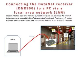
Air-interface connections • In some circumstances it is necessary to transmit to the receiver without having to connect directly to the receiver under test • Where no coaxial connection exists (PDA’s phones…) • Transmission to multiple devices is required • Great care must be taken when radiating the simulated GPS signal • The simulator can easily jam the real GPS for other users in the vicinity (this is illegal in any case) • Signal can become uncontrolled • No establishment of correct RHC polarisation • Uncertain power levels • Strong multiipath • A mixture of simulated an real GPS
Air-interface connections Re-radiation bad practice example ? ?
Air-interface connections Re-radiation good practice example
Re-radiation considerations • Assuming the test-setup is in a controlled anechoic chamber • The receiver is likely to be in the ‘near-field’ of radiation if it is closer than 2 wavelengths from the transmitting antenna (for L1 this is 0.3m) • If establishment of the correct polarisation is required, a Right-Hand Circularly-Polarised transmit antenna is needed, and the tx to rx separation needs to be >0.3m • True path loss must be measured rather than calculated, as the test set-up in a chamber is never ideal. • The gain of the TX antenna and loss of the cable connecting this back to the simulator RF output needs to be taken into account • Only if careful characterisation of the losses is taken into account can meaningful C/No tests be carried out
False locking • A phenomenon unique to a simulator-receiver set-up called false locking can sometimes occur If the simulator power is too high • False locking will prevent a receiver from navigating • The tell-tale signs of false locking are: • The receiver C/No display varies randomly on all channels • The receiver appears to be trying to track satellites that are not being simulated • The answer is simple – turn down the volume! • The level at which false locking occurs will vary between different receivers