Download
1 / 44
450 likes | 642 Views
What makes a DX receiver great? Understanding receiver specs. John Eisenberg K6YP. Agenda. Introduction Receiver fundamentals Sensitivity Linearity Dynamic Range and AGC Function Selectivity Stability Conclusion. Introduction. If you can’t hear him, you can’t work him!

E N D
What makes a DX receiver great?Understandingreceiver specs John Eisenberg K6YP
Agenda • Introduction • Receiver fundamentals • Sensitivity • Linearity • Dynamic Range and AGC Function • Selectivity • Stability • Conclusion
Introduction • If you can’t hear him, you can’t work him! • Hearing him depends on: • Is he on? • Is there decent propagation? • Do you have enough antenna? • How much QRM/QRN is present? • The performance of your receiver. • Today’s talk will focus on receiver performance.
What are you up against? • Weak signals (CW or SSB or a digital mode) • Atmospheric and man made noise (QRN) • Interfering signals (QRM) • Strong signals adjacent to your frequency • Strong signals far removed in frequency • Fast or slow fading (QSB)
What are your weapons • Key receiver performance factors • Sensitivity (Weak signal reception) • Selectivity (Bandwidth matched to signal, Ability to reject adjacent QRM) • Optimum detector for desired signal modulation type • Linearity (Spurious free dynamic range) • Blocking dynamic range (From strong adjacent signals) • Stability (Keep the signal in the pass band)
What this talk will address • Key Receiver Specifications • What are they? • Why each is important? • How to read a QST product review. • I will not address the pros and cons of specific receiver architectures.
Receiver fundamentals • What must a receiver do? • Amplify a weak signal delivered to the receiver by the antenna. • Filter out undesired interfering signals and noise . • Detect the desired signal, extract its intelligence and present the content in a useful format.
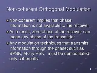
Receiver fundamentals • What must a receiver not do? • Add additional excess noise to the received signal (Degrade SNR) • Generate additional spurious signals or mixer images which corrupt the detection process • Drift off the desired signal frequency
Simple super hetrodyne receiver Antenna Pre- Select Filter AGC Line AGC System Mixer IF Amp BB Amp RF Amp Detector IF Pre- Detect Signal Filter Image Reject Filter IF Roofing Filter Local Oscillator
dB’s and dBm’s • Power ratio in dB = 10log(P2/P1) • Gain in dB = 10log(Pout/Pin) • 3 dB is a factor of 2, 6 dB is a factor of 4 • 10 dB is a factor of 10, 20 dB is a factor of 100 • 39 dB is a factor of 2x2x2x10x10x10 = 8000 • 39 dB is 3+3+3+10+10+10 dB • 0 dBm is 1 milliwatt • Thus +13 dBm is 20 mW, -9 dBm is 1/8 mW
Noise power • Noise is distributed over frequency. • Noise Power is measured “per unit bandwidth” • Example: A noise signal has a uniform power spectral density of -120 dBm/Hz. • Noise power increases by 10log(Bandwidth in Hz) 1 Hz Uniform Noise PSD Bandwidth Total Noise Power 1 Hz -120 dBm 10 Hz -110 dBm 100 Hz -100 dBm 1 MHz -60 dBm PSD dBm/Hz Freq
Receiver sensitivity • Noise Figure = • Noise figure = Input S/N (dB) - Output S/N (dB) Signal/Noise ratio at RX Input Signal/Noise ratio at RX Output Output S/N = 30 dB Input S/N = 40 dB Device with NF = 10 dB
Best possible receiver sensitivity • The noise power from a resistor at 25°C (or a matched antenna in signal free environment) is kTB (Boltzmann’s Constant (k) x Temp (°K) x Bandwidth (Hz). • kTB = -174dBm/Hz This is the noise floor of a noise free receiver at 27 °C . • kTB = 3.98 x 10 watts/Hz at 27°C or about 0.01 V in a 500 Hz bandwidth. -21
Minimum detectable signal • Noise Floor = KTB + NF + 10log(BW in Hz) • MDS = KTB + NF + 10log(BW in Hz) +8 dB • Maybe forOH2BH, MDS = Noise Floor + 5 dB(The 8 dB factor is subjective !) • Often other problems such as reciprocal mixing further degrade MDS
MDS for CW and SSB signals SSB Filter 3 KHz BW (35dB) CW Filter 500 Hz BW (27dB) Minimum Detectable SSB signal -126 dBm Minimum detectable CW signal -134 dBm SSB MDS -126 dBm CW MDS -134 dBm SSB Noise Floor -134 dBm CW Noise Floor -142 dBm Noise Power PSD is -174dBm/Hz +5 db NF or -169 dBm/Hz Noise Floor = -174 dBm/Hz + 5dB NF +10log(BW)
The “standard”S meter Receiver Zin = 50 NF= 10 dB 1 ‘S unit’ = 6 dB S meter reading Signal level in V Signal Level in dBm S9 + 60 dB 50000 -13 S9 + 40 dB 5000 -33 S9 + 20 dB 500 -53 S9 + 10 dB 158 -63 S9 50 -73 S8 25 -79 S7 12.5 -85 S5 3.13 -97 S3 0.78 -109 S2 0.39 -115 S1 0.20 -121 MDS (in a 3 KHz SSB BW) 0.195 -121.2 MDS (in a 250 Hz CW BW) 0.056 -132.0
LO phase noise & reciprocal mixing • Imagine that you are copying a weak signal and all of a sudden a very strong clean carrier pops up 100 KHz from your frequency. • Nothing happens. It is rejected by your receiver’s battery of filters. Right???? • No! Your receivers sensitivity may be degraded by reciprocal mixing with local oscillator (LO) phase noise.
Im(VLO) LO Phase noise VLO Amplitude A +Nam(t) Phase + pn(t) Re(VLO) VLO = (A + Nam(t)) sin[LOt + + pn(t)] The phase noise term pn(t) usually dominates the AM noise Nam(t) LO Spectrum with phase noise 10kHz Offset dBc/Hz Phase noise is often expressed in: dBc/Hz at some carrier offset FLO 1 Hz
Reciprocal Mixing Process Interferer with LO Phase noise Strong Interferer IF Filter Bandwidth Weak Signal LO phase noise on interferer Receiver RX RF input signals RX IF Output BuriedWeak Signal Local Oscillator with Phase Noise LO phase noise on weak signal
Reciprocal mixing -20 dBm Interferer after 1st mixer RX NF = 15 dB, Gain to 1st IF filter after the mixer =10 dB A -20 dBm strong interferer is 100 KHz from desired signal LO phase noise = -110 dBc/Hz at 100 KHz carrier offset IF Filter Bandwidth Desired Signal RX IF Output 100 KHz RX noise floor = KTB+NF+G = -174 dBm/Hz +15 +10 dB = -149 dBm/Hz At 100 KHz away from the -20 dBm interferer phase noise PSD is -110 dBc/Hz -20 dBm = -130 dBm/Hz Adding noise powers in a 1 Hz bandwidth yields ~ -130 dBm/Hz. Thus the Equivalent RX NF with phase noise = 15dB + (-130 +149)dBc/Hz = 34 dB!
Receiver total gain • The lowest noise receiver still must have enough gain to bring the input signal strength up to the level the detector requires to process it. • Both signals and noise are amplified. • Hopefully the signal is well above the noise. • A strong interferer can (and often does) reduce total gain through saturation or AGC action
Receiver sensitivity summary • Noise figure, predetection bandwidth and total gain ideally set receiver sensitivity. • Predetection bandwidth and the detection process must be matched to the signal characteristics. • Spurious signals and mixer images generated in the receiver must be suppressed • LO phase noise in the presence of strong interfering signals can severely degrade receiver sensitivity and usually sets MDS in real world DX situations.
Receiver linearity • Why worry about linearity? • Strong signals close to a weak DX signal can saturate your receiver’s front end or its IF amplifiers dramatically reducing total gain. • Pairs (or multiple) strong interferers can place unwanted intermodulation products on top of that all time new one you are trying to pull in. • These issues compound the previously addressed reciprocal mixing problem.
Gain compression Gain (dB) Linear region Input Power @ 1 dB Gain Compression Small Signal Gain SSG - 1 dB Nonlinear region Saturation region Receiver Input Signal Level (dBm)
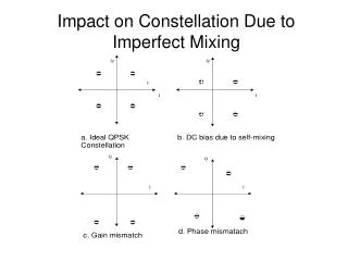
Intermodulation • When 2 or more signals are presented to a nonlinear device, the results are harmonics of each signal and sum and difference products of the signals and their harmonics. These sum and difference products are called intermodulationproducts. Power F1 F2 F1 F2 Even Nonlinear Device Odd Odd Even 2F1 2F2 Freq dc
Intermodulation • Odd order products (IM3, IM5 ....) are close to the original signals and can interfere with another weak close in signal. • Even order products (IM2, IM4 ….) can also cause interference. Usually the receiver’s preselect filter takes care of even order products. (Unless your neighbors are W6YX and W6XX.)
Even order intermodulation Interfering Signal Pair IM product = mF1 ± nF2 Product order is m+n (1F1+1F2), m=1 n=1, Order is 2nd F2 F1 7.10 MHz 7.14 MHz W6YX W6XX F1+F2= 14.240 MHz IM2 Receiver IF Passband F2-F1= 0.04 MHz IM2 2F2-2F1= 0.08 MHz IM4 2F2+2F1= 28.48 MHz IM4 A92BR 14.243 MHz
Odd order intermodulation Interfering Signal Pair F=F2-F1 = 14.2-14.1 =0.1 MHz IM product = mF1 ± nF2 Product Order is m+n (3F1-2F2), m=3 n=2, Order is 5th F2 F1 14.1 MHz 14.2 MHz W6YX W6XX 2F2-F1= 14.3 MHz IM3 2F1-F2= 14.0 MHz IM3 Receiver IF Passband DX0K 14.303 MHz 3F1-2F2= 13.9 MHz IM5 3F2-2F1 =14.4 MHz IM5 F F F F F
Interceptpoint IF Output Power (dBm) Intercept Point Fundamental Signals Linear Region Slope=1 IM3 Slope=3 IM5 Slope=5 RF Input Power (dBm)
Estimating IM level Power (dBm) Order Order Order Order Order 3 3 5 5 7 +40 dBm Intercept Point (dBm) 53 26 20 31 21 dB (dB) -13 dBm Signal Level (dBm) 106 52 80 124 126 dB (P-1) (dB) th P Order IM Level (dBm) -119 dBm Frequency (kHz)
Is your IP3 good enough? • Its close in IMD performance that matters. • A great input intercept point without equally great roofing and predetection filters is worthless! • IIP3 at 5 kHz spacing not 20 kHz counts in a pileup 756 ProIII (20M/500Hz/No Preamp) -17/+25dBm IC7800 (20M/500Hz/No Preamp) +22/+37dBm Source: Mar. 2005 QST Product Review 756ProIII • Don’t forget that -30 dBc IM products from a “20 over 9” perfectly clean SSB signal are > S8! So the problem isn’t always your receiver.
Spurious free dynamic range Power (dBm) +40 dBm Intercept Point (dBm) =54.66 dB, 3rd Order(P=3) -14.66 dBm Signal Level (dBm) SFDR = (-124 dBm) - (-14.66 dBm) =109.33 dB (Noise floor = IM3 level) SFDR (P-1)=109.33 dB, 3rd Order(P=3) th P Order IM Level (dBm) -124 dBm Noise Floor =-174+15+10log 3000= -124 dBm Frequency (kHz)
Receiver gain distribution • Minimize RF gain ahead of the mixer to just enough to achieve required noise figure. Don’t overdrive the mixers thus degrading the receiver’s spurious free dynamic range. Use high IIP3 mixers. • LO phase noise level not NF usually sets real world receiver sensitivity. • Two conversions max! Minimize number of spurs. • Locate the majority of gain after the roofing filter. Keep IM products out of the IF and detectors.
AGC function • AGC reduces the gain of the receiver RF and IF amplifiers in the proper ratio to maintain sensitivity and SFDR in the face of rapidly changing signal levels (QSB). • The analog or DSP detector suite (one for each mode) drives the AGC function. The AGC algorithm should be optimized for each mode.
AGC function • AGC rate must adapt to the mode in use and if possible to the QSB conditions. • Fast attackto minimize pops and thumps • Adaptive decaymatching signal characteristics • AGC holds the detector input level approximately constant as receiver input signal level varies. • Modern DSP based AGC systems can offer vastly improved capability.
Receiver selectivity • Selectivity is determined by the final IF filter • The filter must be matched to the signal characteristics. • Crystal filters are good but they are expensiveand can suffer from ringing and delay distortion. • DSP based filters are generated in code and can be designed for a wide variety of bandwidths, and shape factors. Thus additional filters are almost free. • Best of all DSP filters can greatly reduce ringing.
Receiver selectivity • An excellent receiver has at least 2 crystal roofing filters wide enough to avoid ringing, but narrow enough to reject close in interferers and IM products. For example: 6 - 10 kHz for SSB, 2 - 3 kHz for CW • These would be followed by a choice of DSP filters optimum for various conditions. For example: 3.2, 2.8, 2.4 and 1.8 kHz for SSB, 500 and 250 Hz for CW
Receiver selectivity • The set of DSP filters should allow for various operating conditions such as local rag chewing and intense contest or DX situations. • DSP based filter suites should contain an adaptive notch filter to reduce CW beat notes in the IF pass band (Tuner uppers) • A variable IF band pass filter with selectable center frequency and bandwidth can also be very useful.
Blocking dynamic range • How large can a single CW interferer 20 KHz away from a weak signal be, before the desired signal’s detected level drops 1 dB? • Blocking dynamic range is the difference in level between the weak and strong signals • What happens as the interferer moves closer to the desired signal? How about many close in intereferers as in a pileup.
Blocking dynamic range Signal -100 dBm Interferer -29 dBm IF Po-1 +20 dBm Gain to pre-det’n filter o/p (100dB) Offset Total Signal Interferer from Fo Gain Level Level (kHz) (dB) (dBm) (dBm) Blocking Dynamic Range = 71 dB (3 kHz) 100 99 82 50 49 47 -47 -59 -71 -83 -95 ? ? ? -1 -0.7 -0.3 0 0 0 0 0 0 1 2 3 4 5 7 9 11 13 15 AGC AGC AGC +20 +19.3 +17.7 -76 -88 -100 -112 Noise Interferer -29dBm Gain to roofing filter o/p (50dB) BDR Signal -100dBm Fo-6 kHz Fo+3 kHz Fo-3 kHz Fo+6 kHz Fo
Receiver frequency stability • All modern radios employ synthesized LOs. • Make sure tuning resolution meets your needs • Verify that the synthesizer reference source is stable enough for the digital modes • A 10 ppm TCXO is often a good option to invest in. • A 10 MHz reference output is also a useful feature • Most important .... How’s the phase noise?
DX superhetrodyne receiver Two complete receivers with Split/Dual Watch capability Simple, maximum of 2 conversions Engineered to minimize IF spurious Just enough gain ahead of 1st mixer to set noise floor Take advantage of near perfect DSP linearity Very high input intercept point High performance pre-selctor Multiple high performance matched roofing filters Stable, low phase noise DDS/DSP LO Fast IF DSP (MHz), High resolution A/D & D/A Optimized AGC algorithms for each mode Several filter choices for each mode Effective auto notch and dual passband tuning Adaptive Noise reduction and noise blanker Separate optimum detectors for each mode Intuitive, ergonomic user interface, RTTY built in Straight forward computer interface Antenna Pre- Select Filter AGC Line AGC System Mixer IF Amp BB Amp RF Amp Detector Image Reject Filter IF Roofing Filter IF Matched Signal Filter Analog DSP Local Oscillator
Conclusion • My Priorities • Close in (5 kHz) phase noise Phase noise usually sets receiver sensitivity, not noise figure. If you can’t hear him in the pileup, you can’t work him! • Close in (5 kHz) input intercept. You still can’t hear him if he is wiped out by IM3 from strong stations. • Close in (5 kHz) blocking dynamic range. Analysis has convinced me that long before BDR becomes an issue, reciprocal mixing has buried the new one I am trying to hear.
Conclusion • Rigs with great dual receivers, terrific specs and good bang for the buck are very important but ....... • Don’t neglect front panel ergonomics, an intuitive user interface and well thought out menus and control functions. • You will most likely using this radio for many years. Get the rig that is right for you! • Thanks for coming. See you in the pileups!